Injection molding machine

a technology of injection molding machine and belt tension, which is applied in the direction of gearing details, gearing, instruments, etc., can solve the problems of reducing belt tension, lag in injection molding machine operation, and stopping so as to prevent lag in operation and stoppage of injection molding machine, reduce belt tension

Pending Publication Date: 2021-03-04
FANUC LTD
View PDF2 Cites 2 Cited by
  • Summary
  • Abstract
  • Description
  • Claims
  • Application Information

AI Technical Summary

Benefits of technology

[0004]In an injection molding machine having a belt transmission mechanism, damage to the belt, such as cracks etc., reduces belt tension and causes lag in operation of the injection molding machine. Further, the in...

Problems solved by technology

In an injection molding machine having a belt transmission mechanism, damage to the belt, such as cracks etc., reduces belt tension a...

Method used


Image

  • Injection molding machine
  • Injection molding machine
  • Injection molding machine

Examples


Embodiment Construction

[0018]The injection molding machine according to the present invention will be described in detail below in connection with preferred embodiments while referring to the accompanying drawings.

1. Configuration of Injection Molding Machine 10

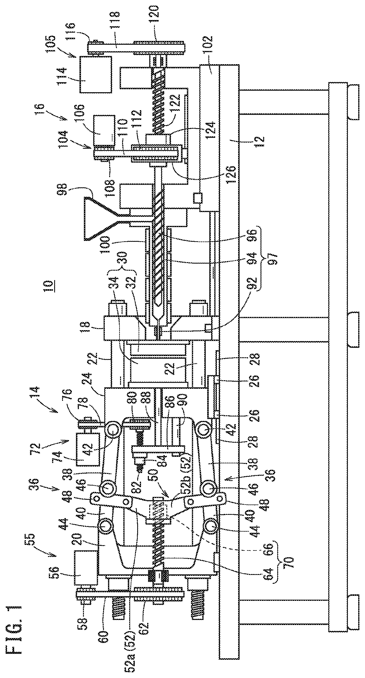
[0019]FIG. 1 is a schematic diagram illustrating the configuration of an injection molding machine 10. The injection molding machine 10 includes a base 12, and a clamping device 14, and an injection device 16 provided on the base 12.

[1.1. Configuration of Clamping Device 14]

[0020]The clamping device 14 includes a stationary platen 18, a rear platen 20, and four tie bars 22. The four tie bars 22 couple the stationary platen 18 and the rear platen 20. The four tie bars 22 are arranged so that their axial directions are parallel to each other. A movable platen 24 is provided between the stationary platen 18 and the rear platen 20. The movable platen 24 is provided on the base 12 with a sliding unit 26 interposed therebetween. The sliding unit 26 can m...


PUM

PropertyMeasurementUnit
Temperatureaaaaaaaaaa
Forceaaaaaaaaaa
Phaseaaaaaaaaaa

Abstract

An injection molding machine includes a belt transmission mechanism (mold opening/closing mechanism, ejector mechanism, screw drive mechanism, injection mechanism) configured to transmit drive force from a driving shaft (driving pulley) to a driven shaft (driven pulley) by means of a belt. The injection molding machine includes: a cover covering part or entirety of the belt; and a sensor attached to the cover and configured to detect an abnormality of the belt.

Description

CROSS-REFERENCE TO RELATED APPLICATION[0001]This application is based upon and claims the benefit of priority from Japanese Patent Application No. 2019-158907 filed on Aug. 30, 2019, the contents of which are incorporated herein by reference.BACKGROUND OF THE INVENTIONField of the Invention[0002]The present invention relates to an injection molding machine having a belt transmission mechanism that transmits drive force from a driving shaft to a driven shaft by means of a belt.Description of the Related Art[0003]Japanese Laid-Open Patent Publication No. 2012-161995 discloses an injection molding machine having a belt transmission mechanism that transmits drive force (power) from a driving shaft to a driven shaft by means of a belt. The injection molding machine includes a driving pulley on the driving shaft side, a driven pulley on the driven shaft side, a belt for transmitting drive force from the driving pulley to the driven pulley, and a sound-proof cover covering the driving pull...

Claims


Application Information

Patent Timeline
IPC IPC(8): B29C45/76F16H7/02F16H57/01G01D5/00G01N21/89B29C45/17B29C45/78B29C45/70
CPCB29C45/768F16H7/02F16H57/01G01D5/00F16H2057/012B29C45/1775B29C45/78B29C45/706G01N21/8901B29C45/76B29C45/661B29C2945/76163B29C2945/7623B29C45/84B29C2945/76093B29C2945/76214B29C2945/76247B29C2945/76464B29C2945/76471B29C2945/76451
Inventor SUGAHARA, KEISUKE
Owner FANUC LTD
Why Eureka
Try Eureka