
Coupling system

a technology of coupling system and plug unit, which is applied in the direction of transportation and packaging, towing devices, vehicle components, etc., can solve the problems of not being able to provide a coupling system, and achieve the effect of preventing oscillation of the plug unit with large amplitude relative to the kingpin, smooth rotation, and advantageously selected tightly

Active Publication Date: 2021-03-04
SAF HOLLAND GMBH
View PDF14 Cites 0 Cited by
  • Summary
  • Abstract
  • Description
  • Claims
  • Application Information

AI Technical Summary

Benefits of technology

[0019]It is advantageous that the actuating section is designed as a threaded spindle. A gear driven by an electric motor can be directly connected to an actuating section designed as a threaded spindle. As an alternative to the threaded spindle design, the actuating section can also be connected to a piston of a pneumatic cylinder or be integrally connected to it in order to cause a movement of the piston into a movement of the adjuster unit parallel to the adjusting axis.
[0020]Preferably, the first plug unit has an essentially cylindrical outer geometry, wherein a retaining flange is formed on the cylindrical outer geometry of the first plug unit. The cylindrical outer geometry of the first plug unit allows its use inside a kingpin. The retaining flange serves to prevent displacement parallel and preferably also transverse to the plug-in axis relative to the kingpin while simultaneously allowing rotation about the plug-in axis relative to the kingpin. As an

Problems solved by technology

So far, however, it has not been possible to provide a coupling system for a fifth wheel coupling in which a large number of different lines on t

Method used


Image

  • Coupling system
  • Coupling system
  • Coupling system

Examples


Embodiment Construction

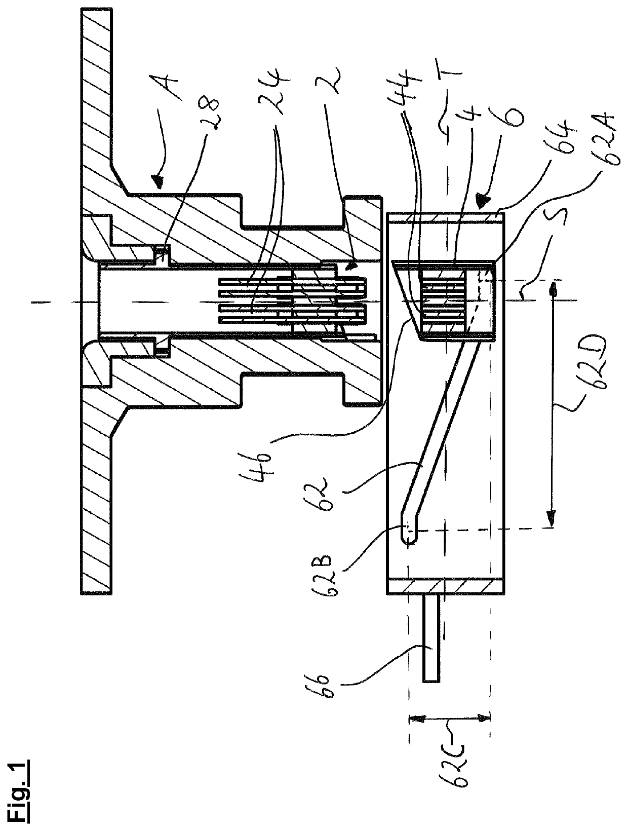
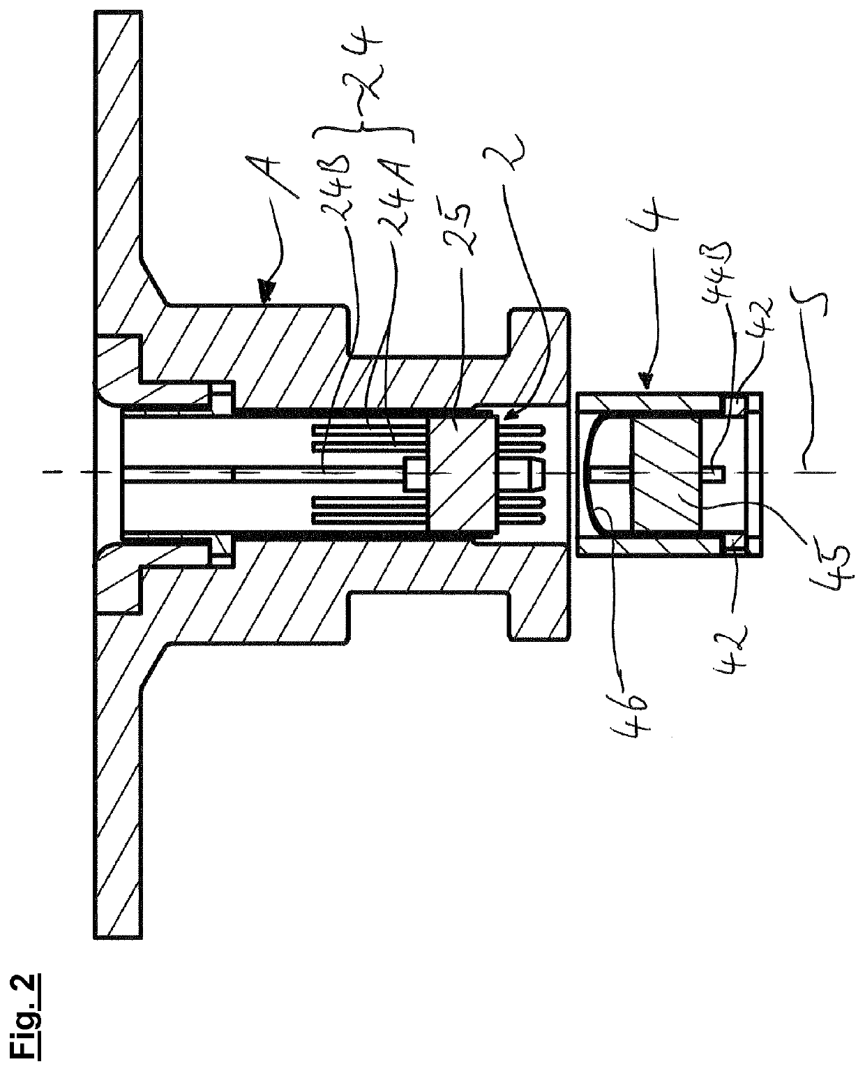
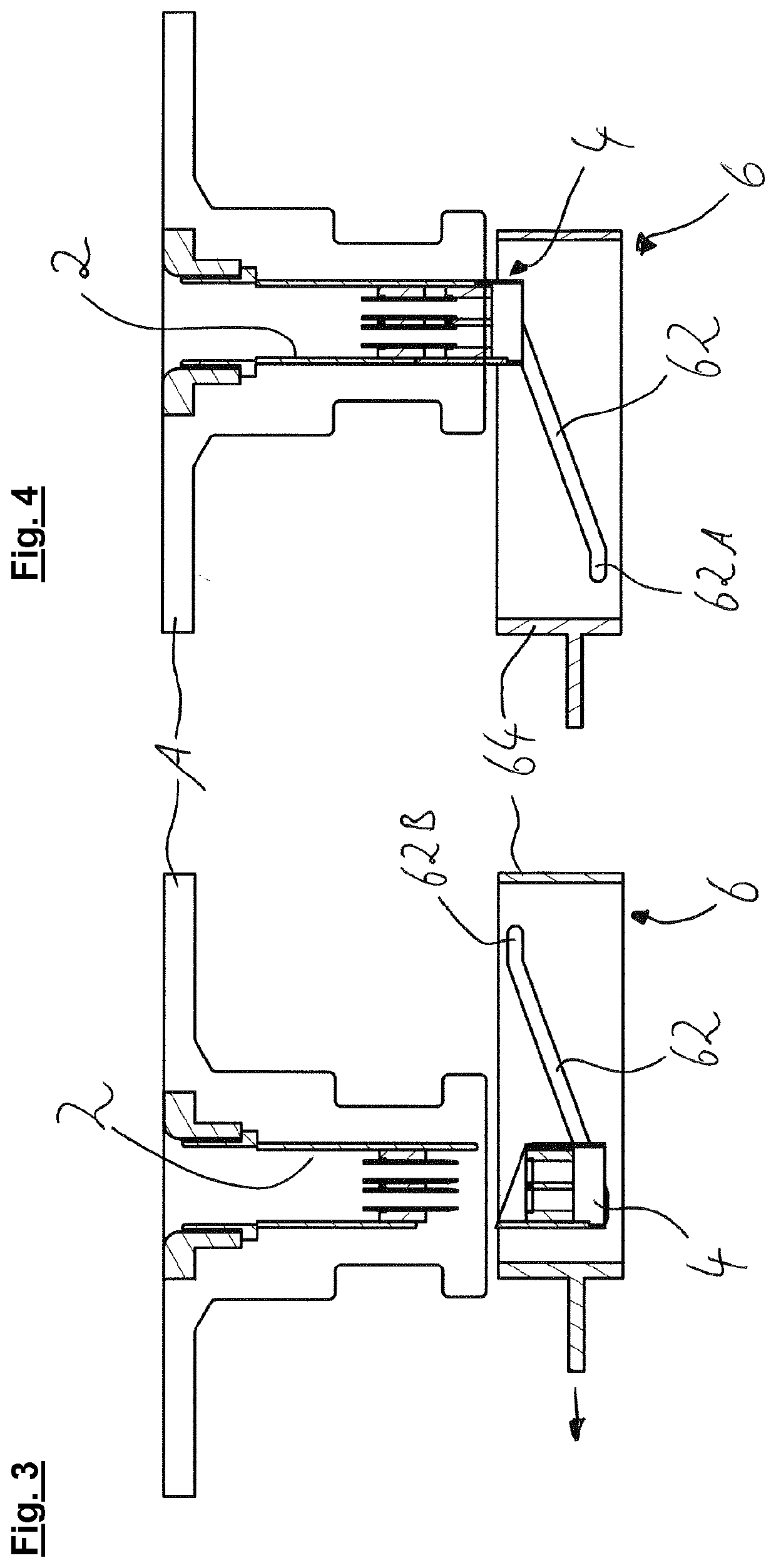
[0031]The preferred embodiment of the coupling system shown in FIG. 1 shows a kingpin A in a position where it is fixed to a coupling plate B of the fifth wheel coupling not shown. In this position a first plug unit 2 and a second plug unit 4 are opposite each other and are offset to each other along a plug-in axis S. The second plug unit 4 is preferably mounted on the coupling plate B (not shown) of a fifth wheel coupling in such a way that movement is only possible along the plug-in axis S. Also mounted on the coupling plate B is an adjuster unit 6, which can be displaced transversely to the plug-in axis S and, in particular, preferably parallel to an adjusting axis T relative to the coupling plate B and the second plug unit 4. The adjuster unit 6 has a housing 64 with a guide section 62, which has an offset 62C of a first distal end 62A and a second distal end 62B. When the adjuster unit 6 shown in the figure is displaced to the right, at least one retaining element 42 provided o...


PUM


Abstract

A coupling system for a fifth wheel coupling includes a first plug unit having a plurality of first plug connectors, and a second plug unit having a plurality of second plug connectors to engage and transmit power and/or fluid with the first plug connectors, and an adjuster unit having a guide section configured to be brought into engagement with a retaining element on one of the plug units to transmit a force from the adjuster unit to the plug unit, which displaces the plug unit along a plug-in axis, wherein the adjuster unit can be displaced transversely and laterally to the plug-in axis or can be rotated about the plug-in axis.

Description

BACKGROUND OF THE INVENTION[0001]The present invention concerns a coupling system for a fifth wheel coupling.[0002]Coupling systems for fifth wheel couplings as such are known from the state of the art. It is also known and common practice to establish various line connections between the towing vehicle and the trailer for the compressed air and energy supply of the trailer of a utility vehicle. Usually elastic and preferably spiral-shaped lines are used for this purpose directly between fixed sockets on the towing vehicle and the trailer. Recently, attempts have also been made to find ways of transferring energy from the towing vehicle to the trailer directly in the area of the mechanical coupling, i.e. in the area of the coupling plate and the kingpin. So far, however, it has not been possible to provide a coupling system for a fifth wheel coupling in which a large number of different lines on the towing vehicle and on the trailer can be connected to each other and at the same tim...

Claims


Application Information

Patent Timeline
IPC IPC(8): B62D53/08B60D1/01
CPCB62D53/0842B62D53/125B60D1/015B60D1/64
Inventor KÖSTER, MARIO SEBASTIAN
Owner SAF HOLLAND GMBH
Learn More