Enhanced idler shaft interface for improving structural integrity of flywheel housing

Active Publication Date: 2021-03-04
CUMMINS INC
View PDF0 Cites 0 Cited by
  • Summary
  • Abstract
  • Description
  • Claims
  • Application Information

AI Technical Summary

Benefits of technology

The present disclosure provides an idler shaft used in an engine that connects a gear cover and a cylinder block. The idler shaft can be sandwiched between the gear cover and the cylinder block or placed in a gapless disposition during use. The idler shaft can be fastened to the gear cover and the cylinder block using at least one fastener. The idler shaft can also have an integral body that provides a clamp load and axial sealing between the gear cover and the cylinder block. The idler shaft can also have a passage way fluidly connected to the cylinder block and / or the gear cover for transmitting fluid for the engine. The technical effects of the present disclosure include improved stability and sealing between the gear cover and the cylinder block, as well as efficient fluid transmission.

Problems solved by technology

However, after experiencing the unwanted movement over a time period, the rigidity of idler shaft 20 during the power transfer from crankshaft 14 to flywheel can be compromised due to displacement of idler shaft 20, and thus a drive line in engine 10 can also become misaligned causing additional harm to engine 10.
As such, conventional idler shaft 20 is less desirable under a vibration harshness condition.
However, during the vibration harshness condition, the attached conventional idler shafts can become loose or pushed outwardly in a radial direction causing further unwanted vibrations and radial movement.
Such movement can cause not only unwanted noise but also premature bearing / gear teeth wear and drive line misalignment.
For example, during a cold engine-start condition, such venting, supply, and drainage operations can be compromised because drain, supply, and vent passage ways can be readily obstructed by ice or other frozen substances.

Method used


Image

  • Enhanced idler shaft interface for improving structural integrity of flywheel housing
  • Enhanced idler shaft interface for improving structural integrity of flywheel housing
  • Enhanced idler shaft interface for improving structural integrity of flywheel housing

Examples


Embodiment Construction

[0023]For the purposes of promoting an understanding of the principles of the disclosure, reference will now be made to the embodiments illustrated in the drawings, which are described below. It will nevertheless be understood that no limitation of the scope of the disclosure is thereby intended. The disclosure includes any alterations and further modifications in the illustrated device and described method and further applications of the principles of the disclosure, which would normally occur to one skilled in the art to which the disclosure relates. Moreover, the embodiments were selected for description to enable one of ordinary skill in the art to practice the disclosure.

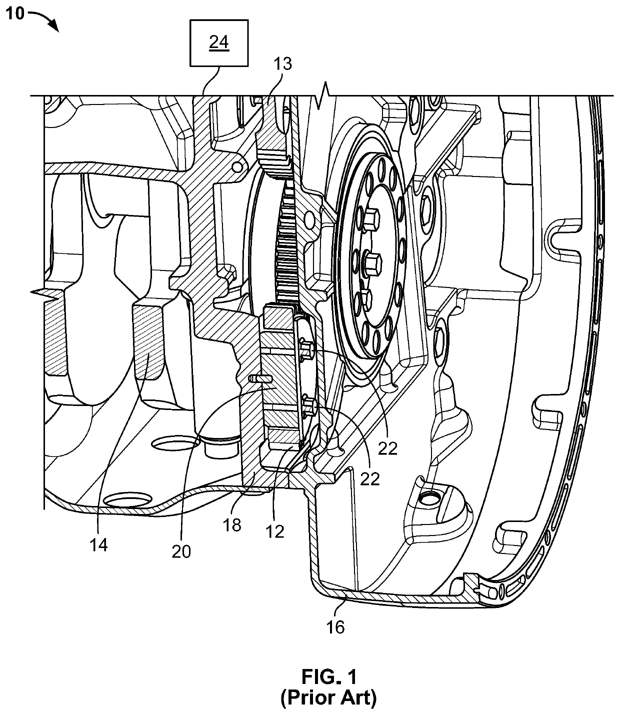
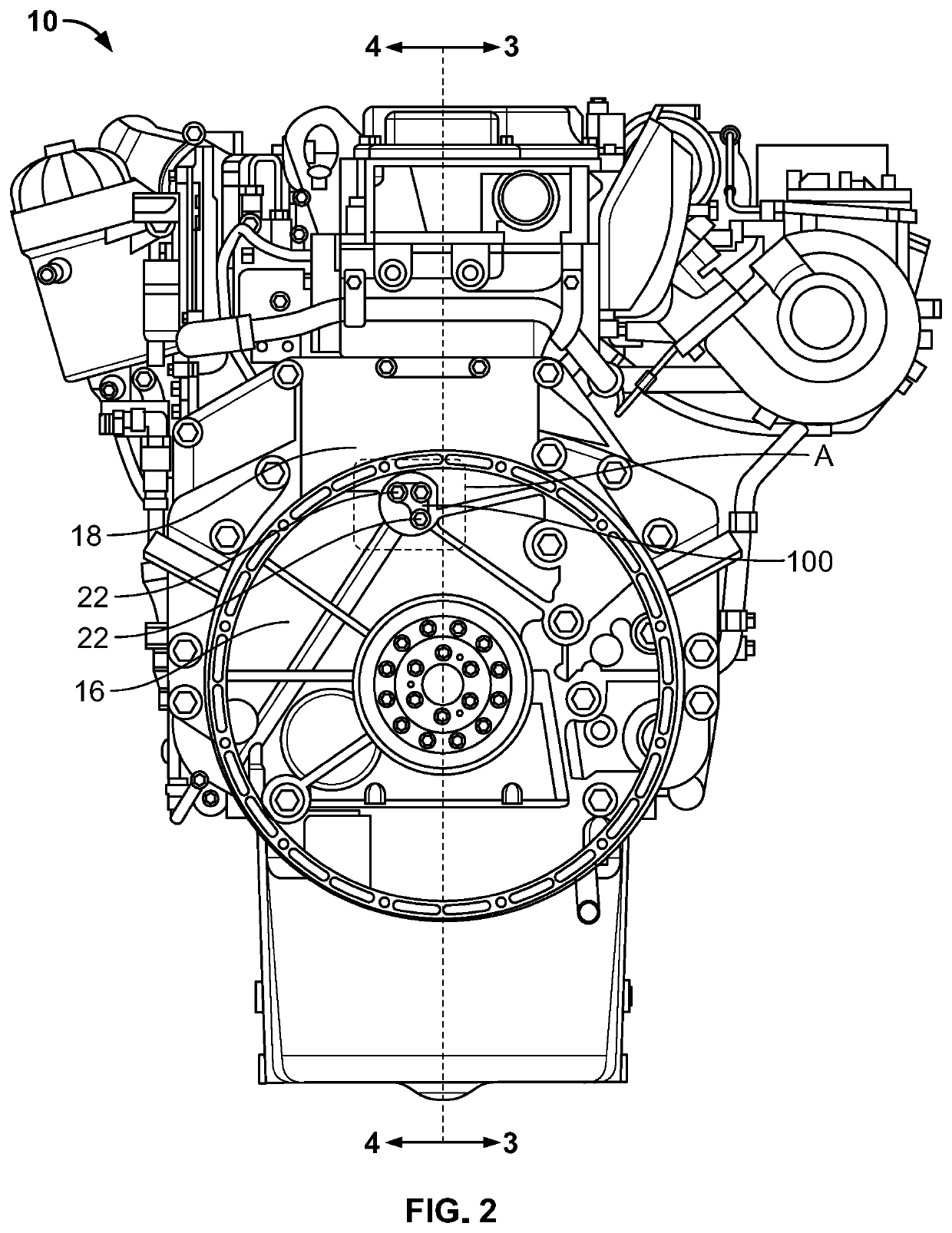
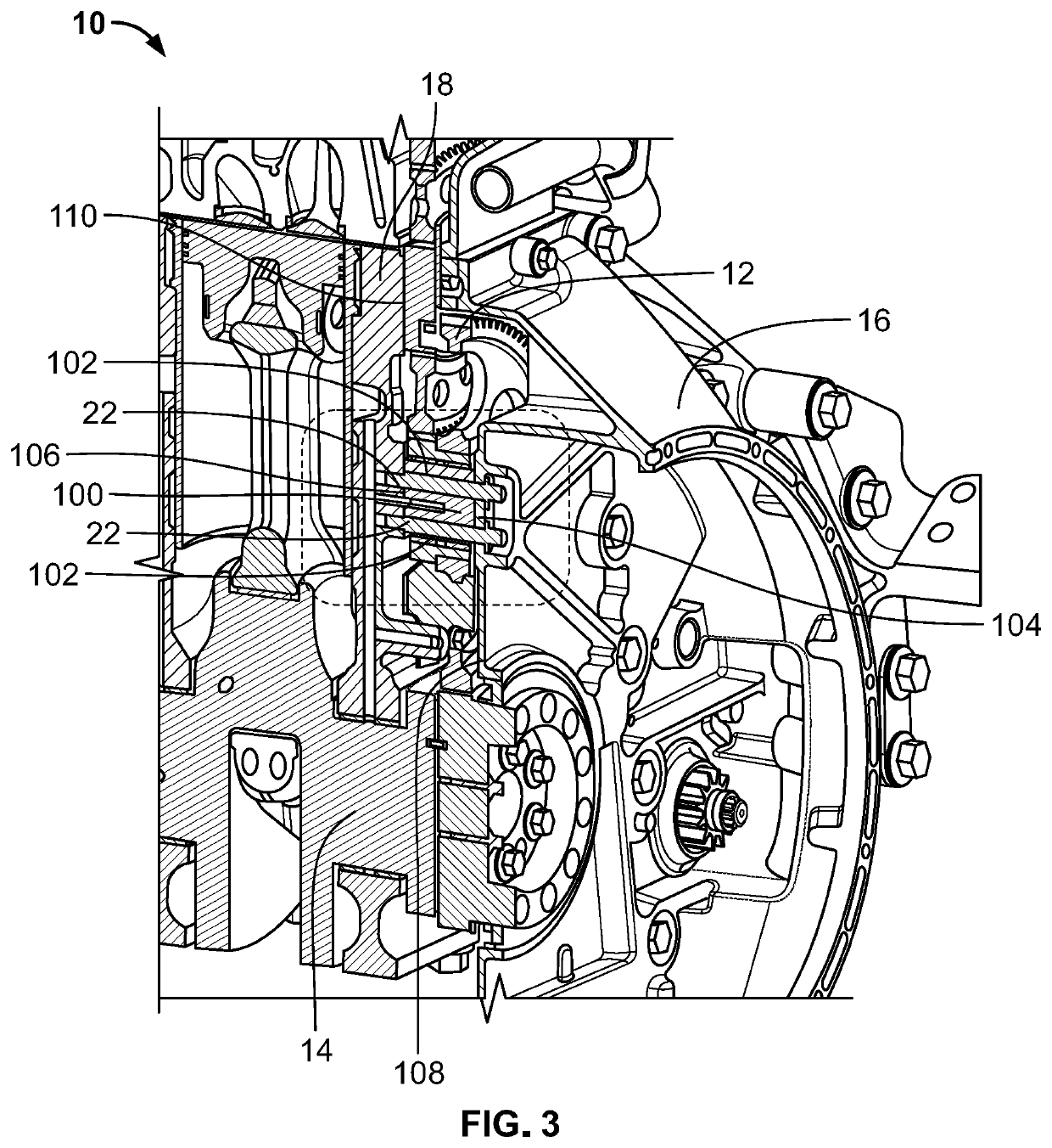
[0024]Referring now to FIGS. 2 and 3, engine gear train 10 having an enhanced idler shaft 100 (“EI shaft” hereinafter) according to one embodiment of the present disclosure is depicted. Like components have been given the same reference designations. In FIGS. 2 and 3, crankshaft 14 (partially shown with counter...


PUM


Abstract

An idler shaft (100) used in an engine (10) having a gear cover (16) and a cylinder block (18). The idler shaft (100) includes an integral body (114) having a cylindrical shape. The idler shaft (100) is compressed between the gear cover (16) and the cylinder block (18) when assembled together such that the integral body (114) of the idler shaft (100) provides a clamp load and axial sealing between the gear cover (16) and the cylinder block (18). The idler shaft (100) further includes a passage way (116) fluidly connected to at least one of: the cylinder block (18) and the gear cover (16) for accommodating transmission of a fluid for the engine (10).

Description

FIELD OF THE DISCLOSURE[0001]The present disclosure generally relates to idler shafts used in engine gear trains and more particularly relates to an idler shaft that improves structural integrity on the engine gear trains.BACKGROUND OF THE DISCLOSURE[0002]Referring now to FIG. 1, an engine gear train, generally designated 10, includes a mechanical system having one or more gears 12, 13 configured to transfer mechanical power from a rotatable crankshaft 14 to accessories or components elsewhere within engine 10. Typically, flywheel and associated gears 12, 13 are enclosed by a gear cover 16 attached to a cylinder block 18 of engine 10. During operation, rotation of crankshaft 14 drives the one or more gears 12, 13 disposed between gear cover 16 and cylinder block 18 to transmit the mechanical power to other components of engine 10. A certain gear 12 can be supported by a conventional stationary idler shaft 20 and bearing assemblies (not shown), including appropriate lubricating syste...

Claims


Application Information

Patent Timeline
IPC IPC(8): F02B67/04F16C3/02F02F11/00F01M13/00F01M11/02F01M11/00
CPCF02B67/04F16C3/02F01M11/0004F01M13/00F01M11/02F02F11/00
Inventor BARNES, DAVID M.AUGUSTIN, SR., KEVIN C.
Owner CUMMINS INC
Why Eureka
Try Eureka