Enhanced method and arrangement for gas regulation in mineral flotation

Active Publication Date: 2017-07-13
METSO OUTOTEC (FINLAND) OY
View PDF4 Cites 2 Cited by
  • Summary
  • Abstract
  • Description
  • Claims
  • Application Information

AI Technical Summary

Benefits of technology

The present invention provides a method and apparatus for recirculating flotation gases without the need for a large and expensive gas buffer tank. Instead, the gas volume fluctuations are handled by a flushing system comprising an expulsion line and a suction line. This allows for the efficient recirculation of flotation gases, which reduces the amount of gas needed and improves the overall efficiency of the flotation process.

Problems solved by technology

High content of oxygen in a flotation cell is known to increase the consumption of the flotation reagent and increase flotation costs.
In some cases, the flotation reagents used may cause unintentional formation of harmful byproduct gases (e.g. H2S).
However, due to the variability of the volume of natural gases, the sealed flotation system has to have some means to compensate for volume changes.
Also, when the outside temperature or ambient air pressure fluctuates, so has to happen also to the gas inside the system, or otherwise mechanical loading due to internal and external pressure differences are incurred to the flotation machines and piping.
Therefore the existing methods do not allow utilization of a closed system with controlled point of release for expulsed flotation system without a need for expensive and large gas buffer tank.

Method used


Image

  • Enhanced method and arrangement for gas regulation in mineral flotation
  • Enhanced method and arrangement for gas regulation in mineral flotation
  • Enhanced method and arrangement for gas regulation in mineral flotation

Examples


first embodiment

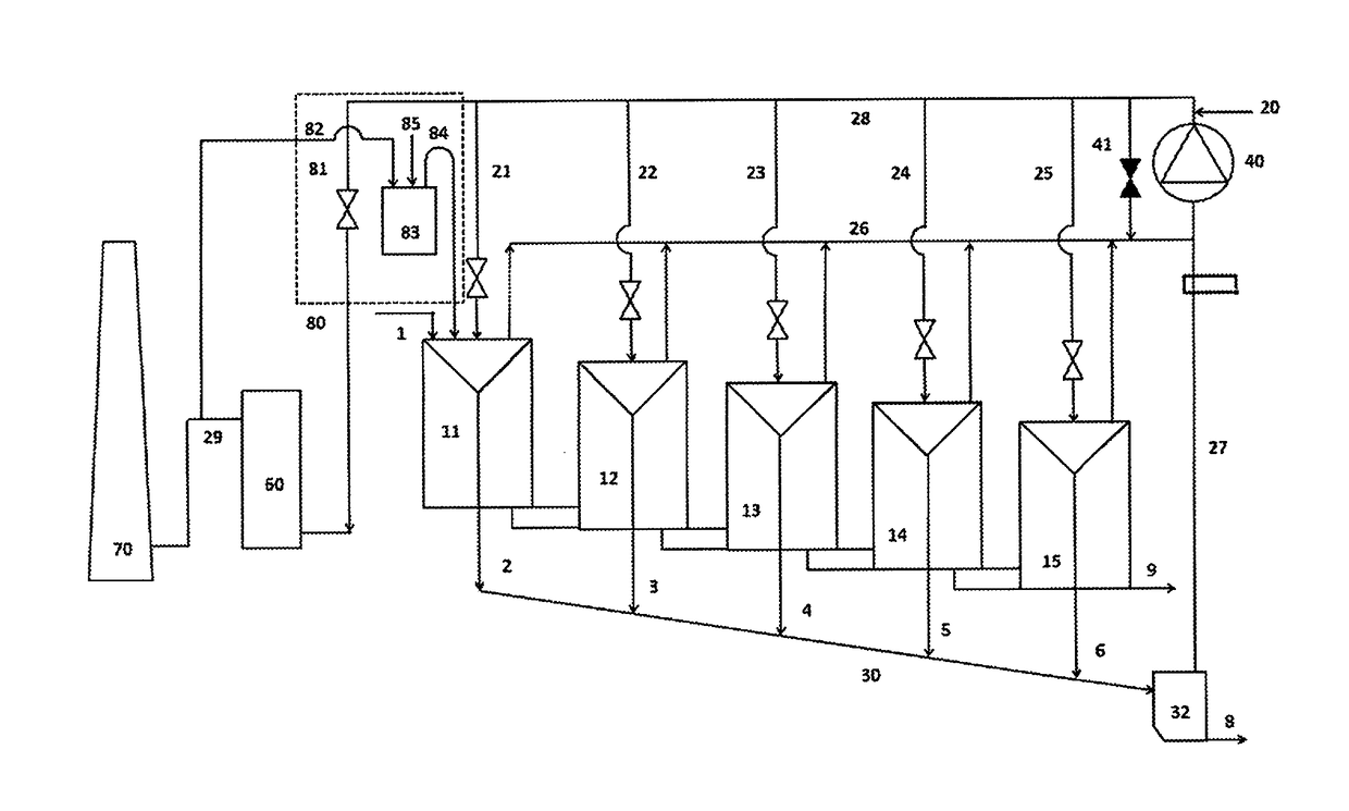
[0053]FIG. 1 illustrates as the invention an arrangement for gas circulation in a mineral flotation process, comprising

[0054]a gas recirculation loop comprising a recirculating compressor 40 for pressurising recirculating flotation gas flow and a gas feed manifold 21, 22, 23, 24, 25 for providing the pressurized recirculating flotation gas into flotation cell units 11, 12, 13, 14, 15, means 20 for providing process gas into the gas recirculation loop, and a gas suction conduit 26 for collecting flotation gas from the headspaces of the sealed flotation cells and transferring it to the recirculating compressor;

[0055]a flushing system 80 comprising an expulsion line 81 for connecting the pressure side 28 of the gas recirculation loop to atmosphere via an optional gas scrubber 60 and a stack 70, for allowing expulsion of a part of the flotation gas from the gas recirculation loop, and a suction line 82, 84 comprising a water lock 83 for connecting the first flotation cell 11 to atmosphe...

second embodiment

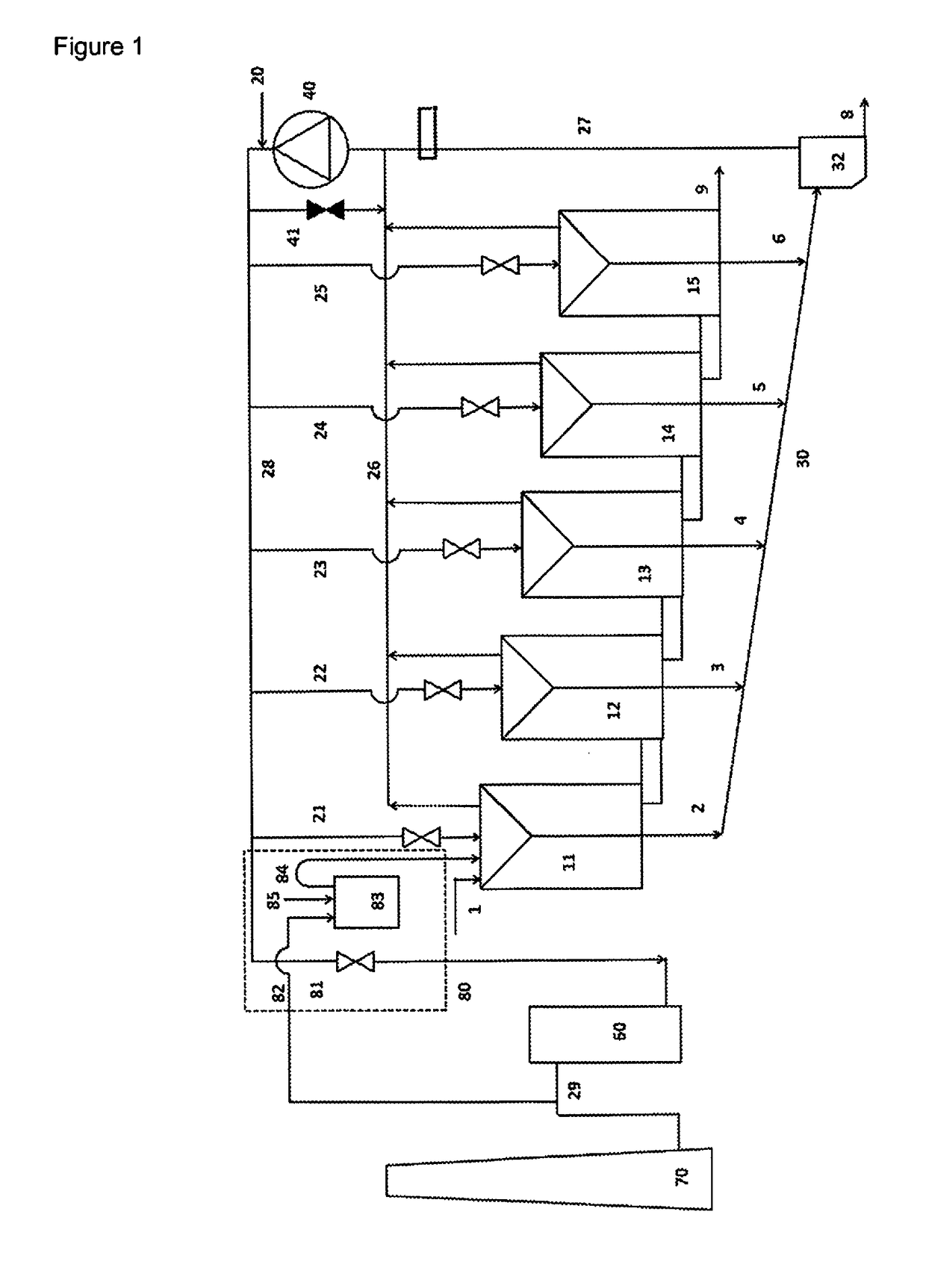
[0064]FIG. 2 illustrates as the invention an arrangement in which the replacement gas is introduced directly into the gas suction conduit. In FIG. 2, like components are designated by the same reference numerals as used in FIG. 1.

[0065]In the flushing system 80 of the embodiment shown in FIG. 2, the expulsion line 81 for connecting the pressure side 28 of the gas recirculation loop to atmosphere is connected via a flushing line 29 comprising a gas scrubber 60 and a stack 70, for allowing scrubbing of the expulsed flotation gas before it is released to atmosphere. The expulsed flotation gas is forced to flow to the scrubber 60 through flushing line 29 by the pressure generated by the compressor or blower 40. The expulsed gas is then scrubbed in the scrubber 60 before releasing to the atmosphere through stack 70.

[0066]The suction line 82, 84 comprising the water lock 83 and connecting the gas suction conduit to atmosphere for allowing gas, present in the flushing line 29, to be withdr...

third embodiment

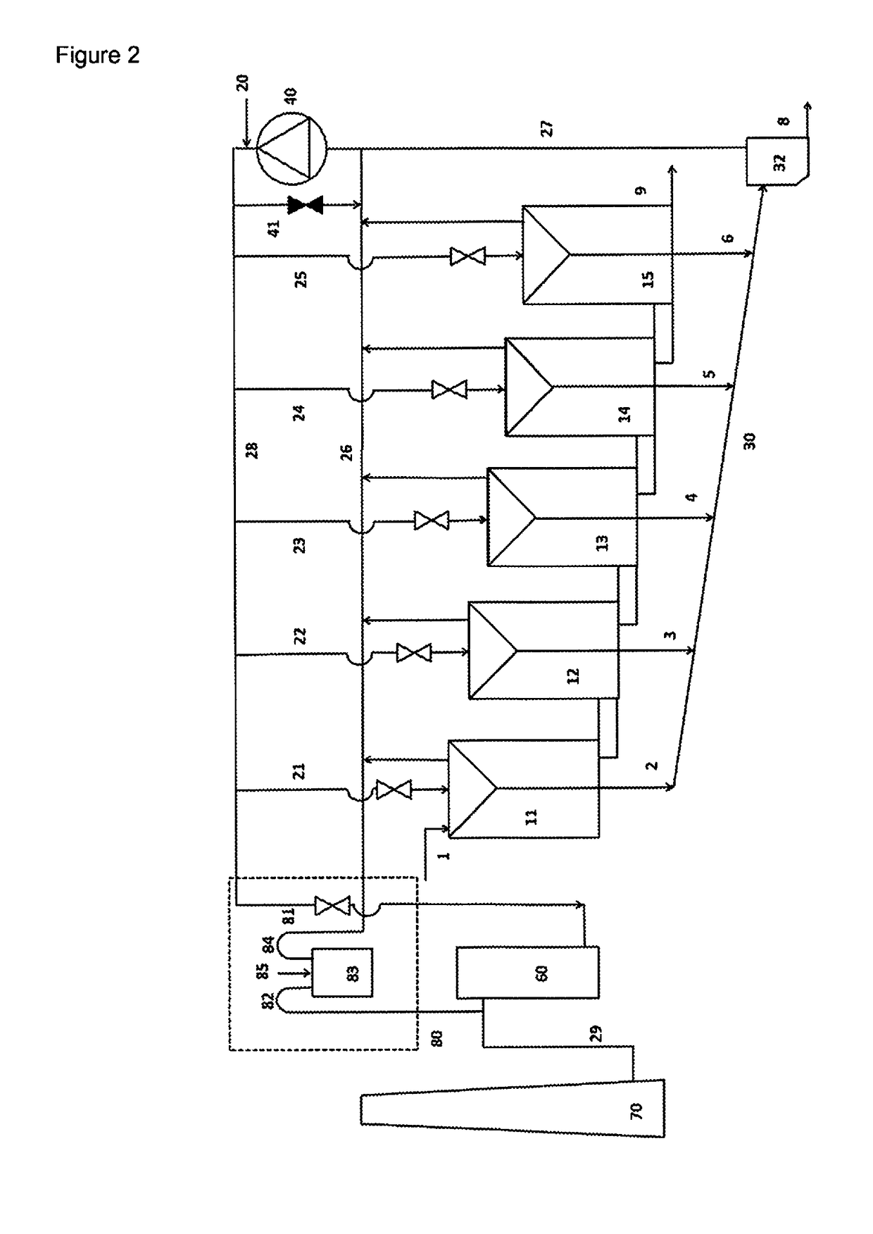
[0067]FIG. 3 illustrates as the invention an arrangement in which the expulsed gas is released directly into the atmosphere without scrubbing and replacement gas is sucked directly in from the atmosphere to the gas suction conduit. In FIG. 3, like components are designated by the same reference numerals as used in FIGS. 1 and 2.

[0068]In the embodiment shown in FIG. 3 in the flushing system 80 the expulsion line 81 for connecting the pressure side 28 of the gas recirculation loop to atmosphere is connected directly to atmosphere allows expulsion of a part of the flotation gas from the gas recirculation loop directly to atmosphere, Similarly the suction line 82, 84 comprising the water lock 83 is connected directly to atmosphere and directly to the gas suction conduit 26 for thus connecting the suction side of the gas recirculation loop directly to atmosphere and for allowing gas, i.e. ambient air, from the atmosphere to be withdrawn directly in to the gas suction conduit 26 through t...


PUM

PropertyMeasurementUnit
Pressureaaaaaaaaaa
Flow rateaaaaaaaaaa
Volumeaaaaaaaaaa

Abstract

A method for controlling gas circulation in a mineral flotation process in a system including one or more flotation cell unit(s) with an apparatus including a gas recirculation loop, a flushing system including an expulsion line for connecting pressure side of the gas recirculation loop to atmosphere and a suction line including a water lock, or means, other than a water lock, for restricting the gas flow and preventing back flow of unpurified gas to the atmosphere, for connecting suction side of the gas recirculation loop to the atmosphere.

Description

FIELD OF THE INVENTION[0001]The present invention relates to a method of controlling gas circulation in mineral flotation for separation of minerals from ore and concentrates, in particularly in separating molybdenum from copper containing sulfide minerals.BACKGROUND OF THE INVENTION[0002]For froth flotation, the ground ore is mixed with water to form a slurry and the desired mineral is rendered hydrophobic by the addition of a surfactant or a collector chemical, such as a depressant, although some mineral surfaces are naturally hydrophobic requiring little or no addition of collector. The particular chemical depends on the nature of the mineral to be recovered and, perhaps, the natures of those that are not wanted. As an example, sodium hydrosulfide (NaHS) may be added as a depressant in the selective flotation of molybdenum to separate it from copper. This slurry of hydrophobic particles and hydrophilic particles is then introduced to tanks known as flotation cells that are aerate...

Claims


Application Information

Patent Timeline
IPC IPC(8): B03D1/24
CPCB03D2203/02B03D1/24B03D1/02B03D1/028Y02P10/20B03D1/14
Inventor LAKANEN, JUKKAGRAU, RODRIGOMIINALAINEN, KAISA
Owner METSO OUTOTEC (FINLAND) OY
Why Eureka
Try Eureka