Image forming apparatus and control program for image forming apparatus

Pending Publication Date: 2021-03-04
KONICA MINOLTA INC
View PDF1 Cites 0 Cited by
  • Summary
  • Abstract
  • Description
  • Claims
  • Application Information

AI Technical Summary

Benefits of technology

The technical effect of this patent is to provide an image forming apparatus and control program that can accurately show the remaining amount of foil roll used in foil stamping printing. This helps the operator to better manage the printing process and ensures consistent quality.

Problems solved by technology

Since foil used in foil stamping printing is awfully expensive, a technique for reducing wasteful consumption of foil is required.
For example, if foil is used up in the part of the way of transfer to paper, paper onto which foil has been transferred in the part of the way is wasted, and the foil that has been transferred to the paper in the part of the way is also wasted.
For example, in the case where the remaining amount of the foil roll at the time of mounting is unknown, such as the case where a foil roll that was used in the past is mounted again, there is a risk of whether the foil is sufficient being not properly determined.

Method used


Image

  • Image forming apparatus and control program for image forming apparatus
  • Image forming apparatus and control program for image forming apparatus
  • Image forming apparatus and control program for image forming apparatus

Examples


Embodiment Construction

[0015]Hereinafter, one or more embodiments of the present invention will be described with reference to the drawings. However, the scope of the invention is not limited to the disclosed embodiments. In the description of the drawings, the same elements are denoted by the same signs, and redundant description will be omitted. The ratio of dimensions in the drawings is exaggerated for convenience of description, and may be different from the actual ratio.

[0016](Image Forming System)

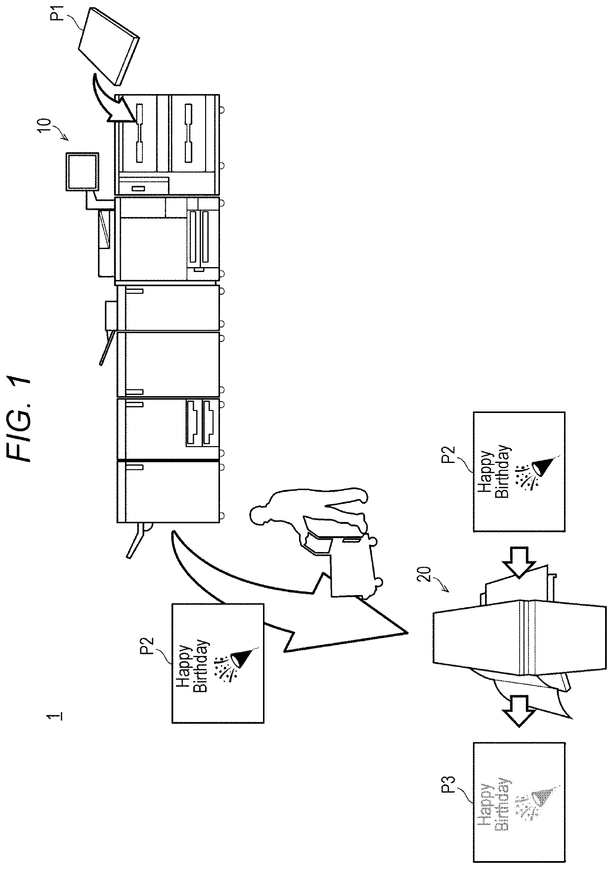
[0017]FIG. 1 illustrates the schematic configuration of an image forming system according to one embodiment of the invention.

[0018]As illustrated in FIG. 1, an image forming system 1 includes an image forming apparatus 10 and a foil stamping apparatus 20.

[0019]The image forming apparatus 10 forms a toner image on paper P1, and outputs paper P2 on which the toner image is formed. Foil is to be transferred to the toner image in foil stamping printing. An operator of the foil stamping printing manually carries...


PUM


Abstract

An image forming apparatus includes: an image former; and a hardware processor that outputs information on a calculation result of a total length, in a paper conveyance directions, of an image part formed at a time of executing a print job by causing the image former to print the information in mirror writing.

Description

[0001]The entire disclosure of Japanese patent Application No. 2019-159773, filed on Sep. 2, 2019, is incorporated herein by reference in its entirety.BACKGROUNDTechnological Field[0002]The present invention relates to an image forming apparatus and a control program for the image forming apparatus.Description of the Related Art[0003]There is known a technique of foil stamping printing. In the technique, paper on which a toner image has been formed is made to overlap foil, and heated and pressurized. Foil is thus transferred to the toner image. Since foil used in foil stamping printing is awfully expensive, a technique for reducing wasteful consumption of foil is required. For example, if foil is used up in the part of the way of transfer to paper, paper onto which foil has been transferred in the part of the way is wasted, and the foil that has been transferred to the paper in the part of the way is also wasted. Techniques of preventing such a situation are required. For example, J...

Claims


Application Information

Patent Timeline
IPC IPC(8): G06K15/02B41N3/00B41F33/00
CPCG06K15/1868B41N3/00B41P2219/20B41F33/00G06K15/021G06K15/022
Inventor MIYAZAKI, KEN
Owner KONICA MINOLTA INC
Why Eureka
Try Eureka