Inductor component

a technology of components and components, applied in the direction of inductances, fixed transformers or mutual inductances, inductances with magnetic cores, etc., can solve the problems of higher probability of electrostatic breakdown in difficult to identify the location of a portion of the base body where an electrostatic breakdown occurs, and may occur, so as to achieve easy correction, easy identification, and easy correction

Active Publication Date: 2021-03-04
MURATA MFG CO LTD
View PDF3 Cites 0 Cited by
  • Summary
  • Abstract
  • Description
  • Claims
  • Application Information

AI Technical Summary

Benefits of technology

[0009]In the case where an electrostatic breakdown occurs between the first substantially columnar line and the third substantially columnar line, the damaged portion of the base body is easily corrected by drilling a hole in the damaged portion with, for example, a laser and then sealing the hole with an insulating resin, such as an acrylic resin.
[0010]Thus, when an electrostatic breakdown occurs in the base body, the location of the damaged portion of the base body is easily identified and is easily corrected.

Problems solved by technology

When such inductor components of the related art were actually produced, the following problems were found.
In production processes of inductor components, electrostatic breakdowns of base bodies may occur.
The distance where the first coil line and the second coil line arrange side by side is long; thus, it is difficult to identify the location of a portion of the base body where an electrostatic breakdown occurs.
This leads to a higher probability of the occurrence of an electrostatic breakdown in a portion of the base body between the first substantially columnar line and the third substantially columnar line than that in a portion of the base body between the first portion of the first coil line and the second portion of the second coil line.
In this case, when the distance Ly is long, it is difficult to identify the location of a damaged portion when an electrostatic breakdown occurs between the first coil line and the second coil line; however, because an electrostatic breakdown occurs easily between the first substantially columnar line and the third substantially columnar line, the location of the damaged portion is easily identified.
In this case, the magnetic layer containing a magnetic metal powder is susceptible to a dielectric breakdown.

Method used


Image

  • Inductor component
  • Inductor component

Examples


first embodiment

[0032]Configuration

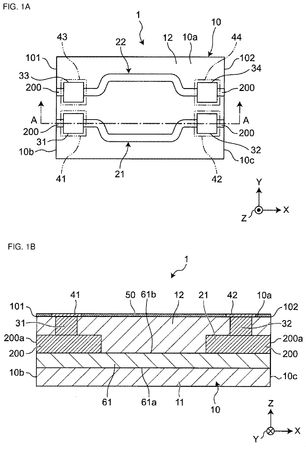
[0033]FIG. 1A is a perspective plan view of an inductor component according to a first embodiment. FIG. 1B is a cross-sectional view taken along line IB-IB of FIG. 1A.

[0034]An inductor component 1 is, for example, a component mounted on a circuit board installed in an electronic device, such as a personal computer, a digital versatile disc (DVD) player, a digital camera, a television (TV) set, a cellular phone, or an automotive electronic system and is, for example, a substantially rectangular parallelepiped component as a whole. The shape of the inductor component 1 may be, but is not particularly limited to, a substantially cylindrical shape, a substantially polygonal columnar shape, a substantially truncated cone shape, or a substantially truncated polygonal pyramid shape.

[0035]As illustrated in FIGS. 1A and 1B, the inductor component 1 includes a base body 10; a first coil line 21 and a second coil line 22 disposed in the base body 10; a first substantially co...

examples

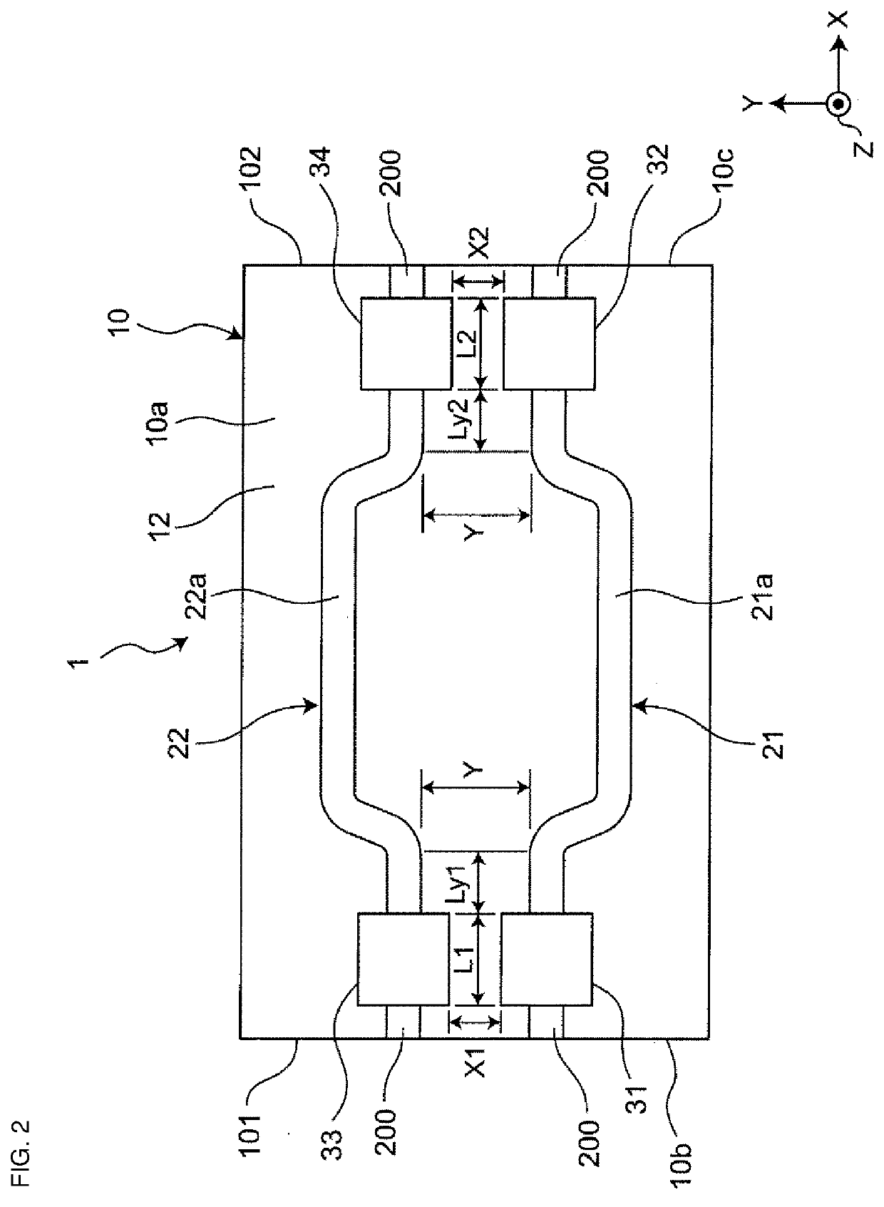
[0083]Inductor components according to the above embodiment were actually produced. As illustrated in FIG. 2, regarding the size of each of the inductor components, the dimension in the Y direction was about 0.5 mm, the dimension in the X direction was about 2 mm, and the dimension in the Z direction was about 0.3 mm. The minimum distance X1 and the minimum distance X2 were equal to each other and defined as a minimum distance X. Inductor components of Examples 1 to 7 and a comparative example with different minimum distances X as given in Table 1 were produced. The minimum distance Y was about 100 μm. Each of the distances L1 and L2 was about 100 μm.

[0084]In Examples 1 to 7 and the comparative example, coil lines having a linear shape when viewed from the Z direction were used. An electrostatic discharge (ESD) test was performed. Table 1 presents the results of ESD evaluation. In the ESD test, ECDM-400EC, available from Tokyo Electronics Trading Co., Ltd., was used. A test method c...


PUM

PropertyMeasurementUnit
thicknessaaaaaaaaaa
thicknessaaaaaaaaaa
thicknessaaaaaaaaaa

Abstract

An inductor component includes a base body, a first coil line and a second coil line, a first substantially columnar line and a second substantially columnar line, and a third substantially columnar line and a fourth substantially columnar line. The first substantially columnar line is located closer to the third substantially columnar line than the fourth substantially columnar line. A minimum distance X1 between the first substantially columnar line and the third substantially columnar line is shorter than a minimum distance Y between a first portion of the first coil line and a second portion of the second coil line.

Description

CROSS-REFERENCE TO RELATED APPLICATION[0001]This application claims benefit of priority to Japanese Patent Application No. 2019-154523, filed Aug. 27, 2019, the entire content of which is incorporated herein by reference.BACKGROUNDTechnical Field[0002]The present disclosure relates to an inductor component.Background Art[0003]Hitherto, a component disclosed in Japanese Unexamined Patent Application Publication No. 2002-217016 has been known as an inductor component. The inductor component include a base body, a first coil line and a second coil line, each being disposed in the base body and parallel to a first main surface of the base body, a first extended line and a second extended line, each being buried in the base body, having an end face exposed at a side face of the base body, and being electrically connected to the first coil line, and a third extended line and a fourth extended line, each being buried in the base body, having an end face exposed at a side face of the base b...

Claims


Application Information

Patent Timeline
Patent Type & Authority Applications(United States)
IPC IPC(8): H01F17/00H01F27/32H01F17/04H01F27/29
CPCH01F17/0013H01F27/32H01F2017/048H01F27/292H01F17/04H01F27/28H01F27/324H01F27/34H01F17/0006H01F2017/0066H01F27/402H01F19/04
Inventor MIYAKE, ISAMUHIRAI, SHINYAHAMADA, AKINORITOMINAGA, RYUICHIROYAMAGUCHI, KOICHI
Owner MURATA MFG CO LTD
Why Eureka
Try Eureka