Divided core of a motor

a motor and divided core technology, applied in the direction of cleaning equipment, electric equipment installation, magnetic circuit shape/form/construction, etc., can solve the problems of large change of magnetic flux density, increase core or iron loss, iron electricity loss, etc., to reduce core loss or back electro-motive force loss, enhance the concentricity of back yoke and teeth, and minimize magnetic resistance loss

Active Publication Date: 2021-03-04
LG ELECTRONICS INC
View PDF0 Cites 0 Cited by
  • Summary
  • Abstract
  • Description
  • Claims
  • Application Information

AI Technical Summary

Benefits of technology

[0022]Another object of the present disclosure is to provide a divided core that may reduce core loss or back electro-motive force (BEMF) loss by minimizing a cut-away surface formed in the divided core.
[0043]Still further, the divided core may enhance productivity by integrally forming a back yoke as one body.

Problems solved by technology

However, the coils are likely to be too concentrated on the slot enough to cause big change of the magnetic flux density and increase core or iron loss, in other words, electricity loss of iron.
However, it is difficult in Cited reference 1 to adjust the concentricity accurately, because the coupling surfaces of the protrusions are coupled to respective divided cores by bonding.
Accordingly, core loss or counter-electric-motive force loss is likely to occur in respective coupling surfaces.
However, in case of Cited reference 3, magnetic resistance rises in a divided surface of the back yoke such that the efficiency of the motor may deteriorate.
Similar to above-noted Cited reference 1, it is difficult to adjust the concentricity accurately because of the error that might occur in a coupling area when the back yokes contact with each other.
In addition, in case of Cited reference 1 through 3, a plurality of divided or cut-away surfaces may be formed such that it may be limited to keep the entire strength of the stator core.

Method used


Image

  • Divided core of a motor
  • Divided core of a motor
  • Divided core of a motor

Examples


Embodiment Construction

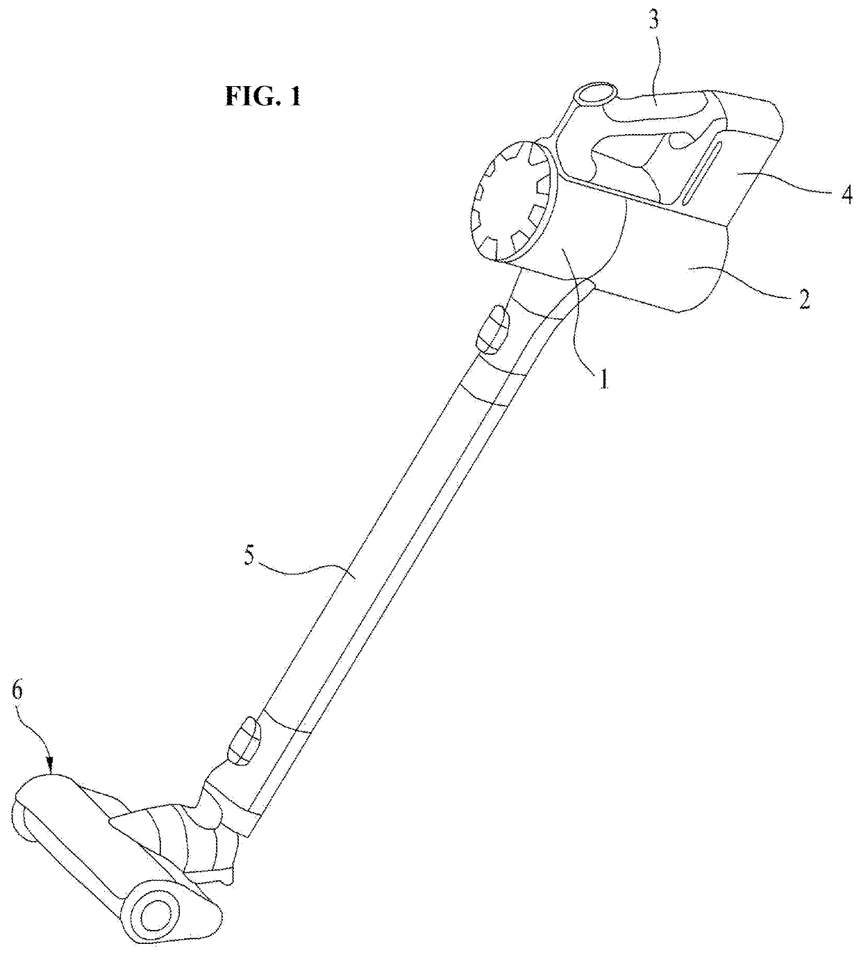
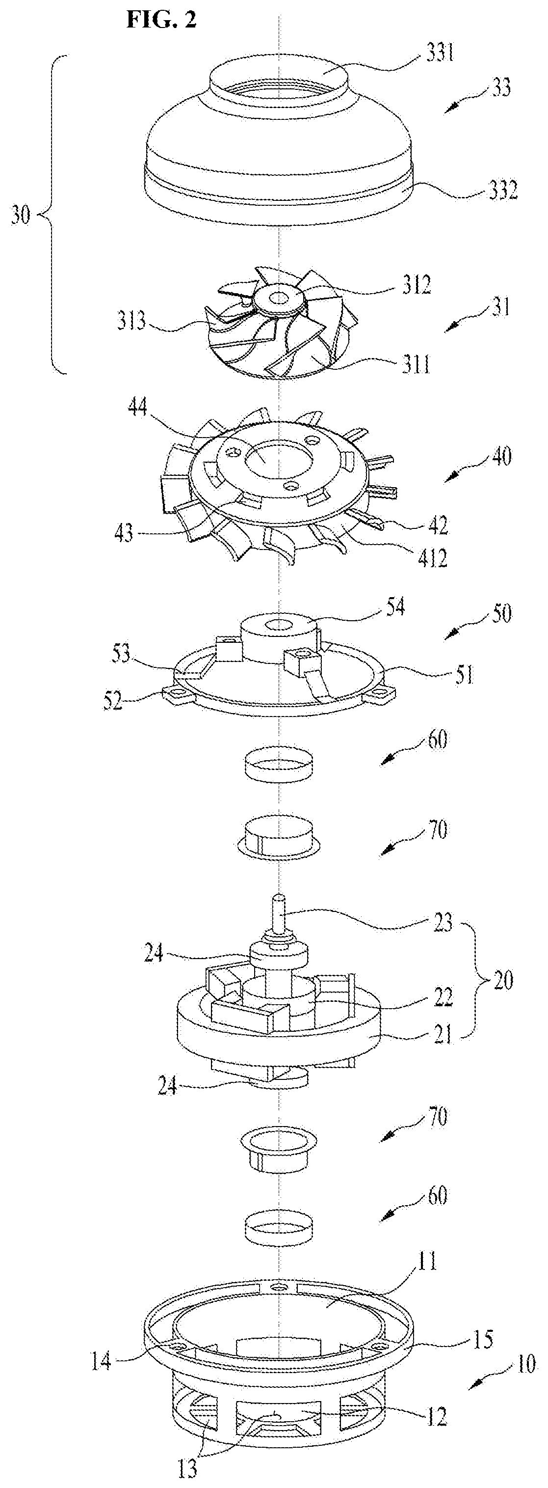
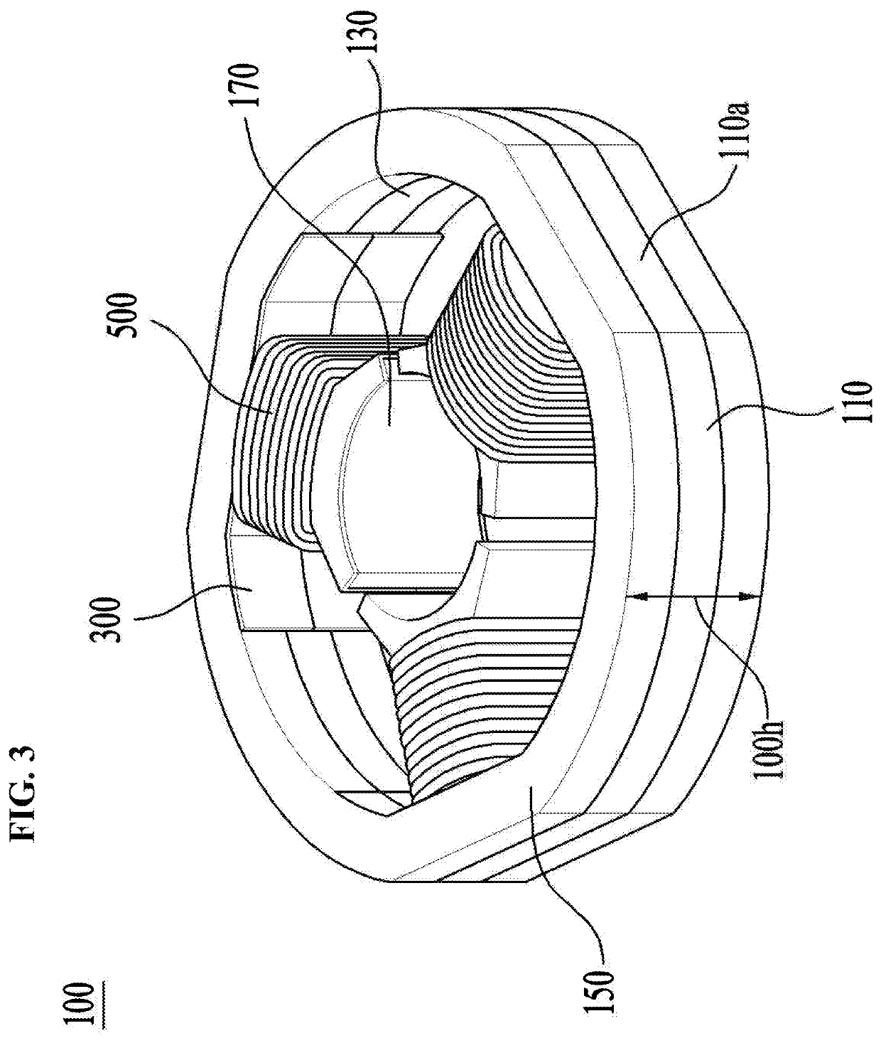
[0056]Referring to the accompanying drawings, exemplary embodiments of the present disclosure will be described in detail. Regardless of numeral references, the same or equivalent components may be provided with the same reference numbers and description thereof will not be repeated.

[0057]Description will now be given in detail according to exemplary embodiments disclosed herein, with reference to the accompanying drawings. For the sake of brief description with reference to the drawings, the same or equivalent components may be provided with the same reference numbers, and description thereof will not be repeated. In the present disclosure, that which is well-known to one of ordinary skill in the relevant art has generally been omitted for the sake of brevity. The accompanying drawings are used to help easily understand various technical features and it should be understood that the embodiments presented herein are not limited by the accompanying drawings. As such, the present disc...


PUM


Abstract

A divided core of a motor includes: a stator core comprising a plurality of core segments; a back yoke forming a circumference of the core segments; and teeth extending from the back yoke towards a radial direction of the back yoke, wherein the plurality of the core segments are disposed along an axial direction of the stator core, and there are some areas where the teeth are overlapped with each other when disposing the core segments.

Description

CROSS-REFERENCE TO RELATED APPLICATIONS[0001]This application claims priority to Korean Patent Application No. 10-2019-0109496 filed on Sep. 4, 2019 in Korea, the entire contents of which is hereby incorporated by reference in its entirety.BACKGROUND OF THE DISCLOSUREField of the Disclosure[0002]Embodiments of the present disclosure relate to a single-phase divided core configured to form a state of a motor.Background of the Disclosure[0003]A conventional motor is a device configured to realize a drive force by using an interaction between a stator and a rotor. The structure of the rotor and stator is basically well known and identical.[0004]However, such a motor is categorized into diverse types based on the rotating principle of the rotor that is rotatable according to the interaction with the stator. Such a motor is often categorized into diverse types based on the type or phase of the electric power applied to a stator coil. In addition, the motor may be categorized into diverse...

Claims


Application Information

Patent Timeline
Patent Type & Authority Applications(United States)
IPC IPC(8): H02K1/14A47L5/28A47L9/22A47L9/28
CPCH02K1/146A47L9/28A47L9/22A47L5/28H02K1/148H02K3/28H02K3/345H02K3/38
Inventor BAE, JONGWOO
Owner LG ELECTRONICS INC
Why Eureka
Try Eureka