Digital Hydraulic system

a digital hydraulic system and digital hydraulic technology, applied in the direction of fluid couplings, instruments, servomotors, etc., can solve the problems of increased efficiency over the throttling method and high initial cost, and achieve the effect of efficient conversion of mechanical power into hydraulic force, and less cooling of hydraulic fluid

Inactive Publication Date: 2009-01-13
DIGITAL HYDRAULICS
View PDF12 Cites 32 Cited by
  • Summary
  • Abstract
  • Description
  • Claims
  • Application Information

AI Technical Summary

Benefits of technology

[0011]An advantage of the present invention is that it can be utilized in four quadrant operation.
[0012]Another advantage of the present invention is that it efficiently transforms mechanical power into hydraulic force and delivers the force with a minimal amount of energy loss.
[0013]Yet another advantage of the present invention is that it requires less cooling of the hydraulic fluid.

Problems solved by technology

Hydrostatic systems result in an increase in efficiency over the throttling method, but at a high initial expense.

Method used


Image

  • Digital Hydraulic system
  • Digital Hydraulic system
  • Digital Hydraulic system

Examples


Embodiment Construction

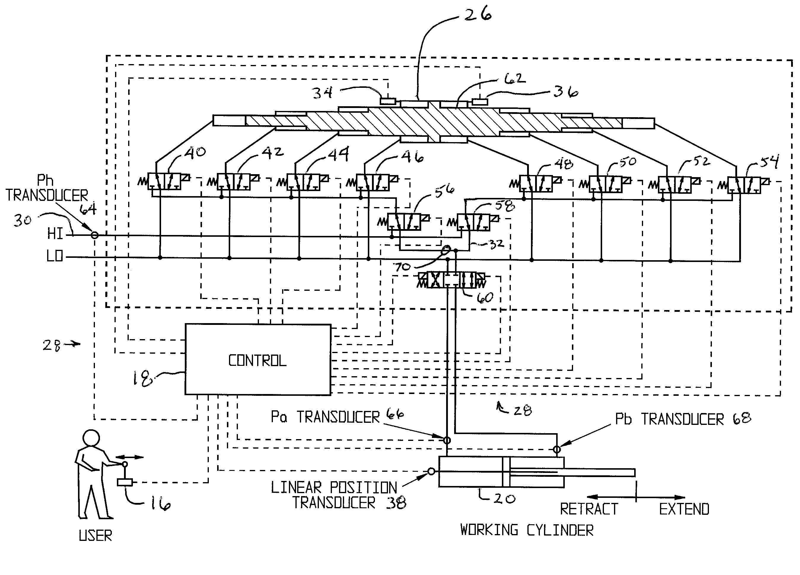
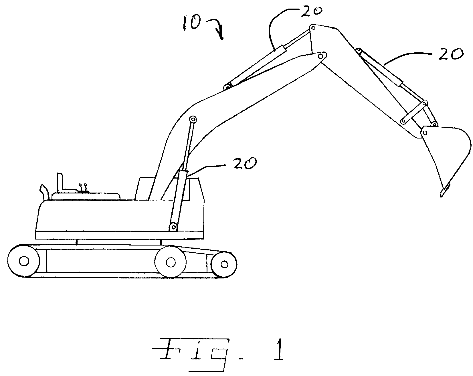
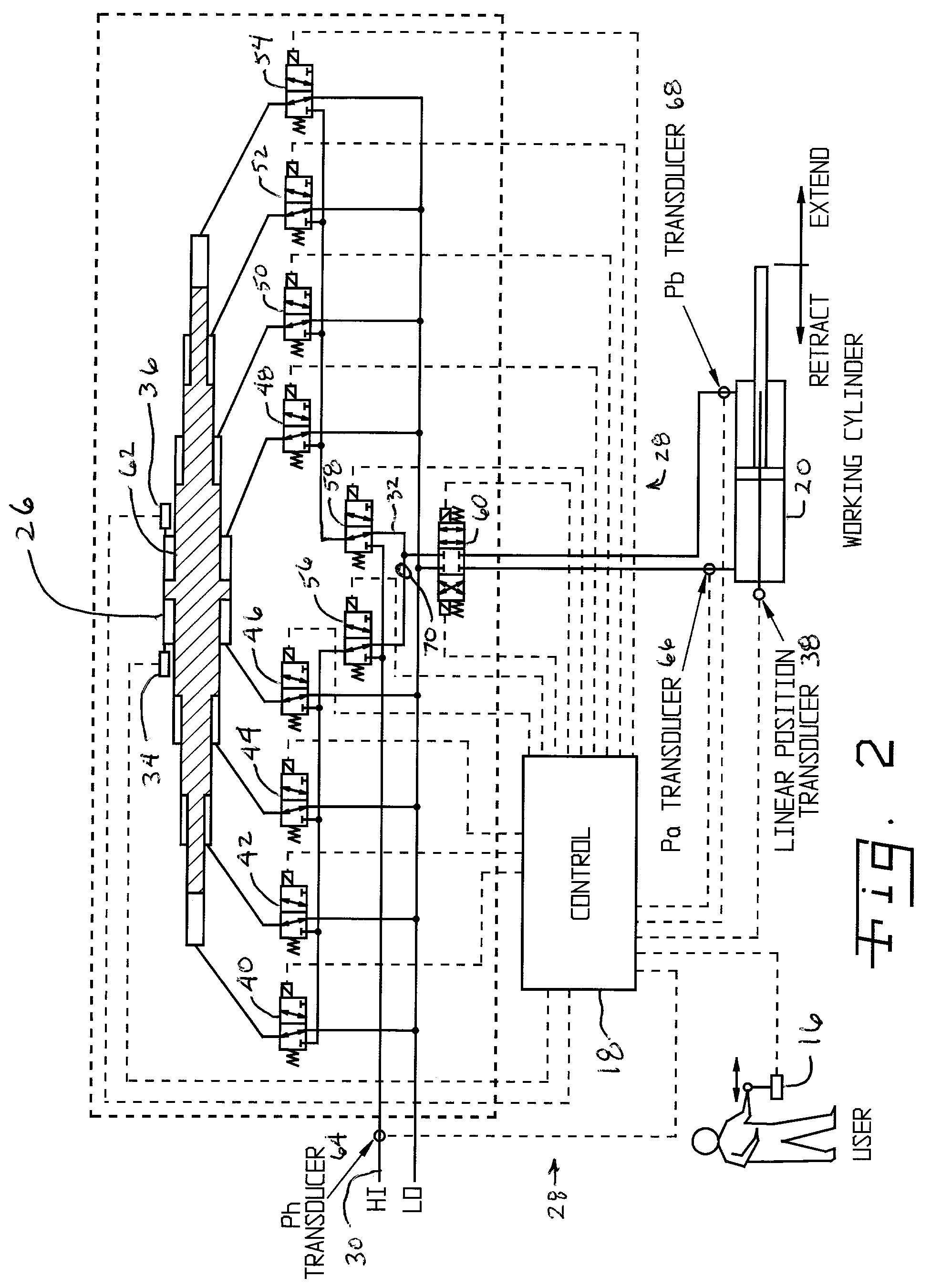
[0026]Referring now to the drawings, and more particularly to FIGS. 1-3, there is shown a digital hydraulic system 10 being used in conjunction with a backhoe assembly. Digital hydraulic system 10 includes a power source 12, a pump 14, a human interface 16, a control system 18, an actuator 20, a buffering device 22, an accumulator 24, a digital hydraulic transformer 26, sense and control lines 28 and hydraulic lines 30 and 32. Power source 12 provides mechanical power to actuate pump 14 to serve as a hydraulic source to provide pressurized fluid / flow to digital hydraulic system 10. Pump 14 can be a typical hydraulic pump or may be a digital hydraulic pump 14 as described herein. Buffering device 22 serves an anti-cavitation function to absorb any impulses that may occur as the hydraulic fluid is switched by control system 18. Additionally, buffering device 22 may serve an accumulation function. Although not illustrated, pump 14 and actuator 20 may have buffering devices associated w...


PUM


Abstract

A digital hydraulic system including a hydraulic source, a housing and a transtatic bridge. The transtatic bridge being substantially contained within the housing. The transtatic bridge being in fluid communication with the hydraulic source. The transtatic bridge communicating a force to or from a shaft or a fluid.

Description

CROSS REFERENCE TO RELATED APPLICATIONS[0001]This is a non-provisional application based upon U.S. provisional patent application Ser. No. 60 / 740,345, entitled “DIGITAL HYDRAULIC SYSTEM”, filed Nov. 29, 2005.BACKGROUND OF THE INVENTION[0002]1. Field of the Invention[0003]The present invention relates to a hydraulic system and method, and, more particularly, to a digital hydraulic system and method.[0004]2. Description of the Related Art[0005]Hydraulics has a history practically as old as civilization itself. Hydraulics, more generally, fluid power, has evolved continuously and been refined countless times into the present day state in which it provides a power and finesse required by the most demanding industrial and mobile applications. Implementations of hydraulic systems are driven by the need for high power density, dynamic performance and maximum flexibility in system architecture. The touch of an operator can control hundreds of horsepower that can be delivered to any location...

Claims


Application Information

Patent Timeline
Patent Type & Authority Patents(United States)
IPC IPC(8): F15B7/00F01B7/00F15B13/04
CPCE02F9/22F15B1/021F15B1/024F15B3/00F15B11/036F15B21/08F15B21/087F15B21/14F15B2211/20569F15B2211/214F15B2211/26F15B2211/30525F15B2211/3111F15B2211/3138F15B2211/327F15B2211/40515F15B2211/41518F15B2211/426F15B2211/45F15B2211/625F15B2211/6309F15B2211/6313F15B2211/6333F15B2211/6336F15B2211/6346F15B2211/6652F15B2211/6655F15B2211/6656F15B2211/6658F15B2211/7053F15B2211/76
Inventor BISHOP, ELTON DANIEL
Owner DIGITAL HYDRAULICS
Why Eureka
Try Eureka