Reclining device

a technology of reclining device and reclining plate, which is applied in the direction of movable seats, vehicle components, vehicle arrangements, etc., can solve the problems of reducing the effective limiting the thickness of the gear teeth and the number of the gear teeth, and reducing the engagement efficiency between the slide gear b>4/b> and the internal gear b>5. , to achieve the effect of reducing the force breaking away the plates, compact and light apparatus,

Inactive Publication Date: 2005-01-18
NHK SPRING CO LTD
View PDF22 Cites 33 Cited by
  • Summary
  • Abstract
  • Description
  • Claims
  • Application Information

AI Technical Summary

Benefits of technology

In accordance with the arranging aspect of the holding member as mentioned above, the holding member always holds the rotary plate in the fixed plate near the engaging position between the slide gear and the internal gear without relation to the position (angle of rotation) of the rotary plate rotating together with the tilt of the seat back. This is because the holding member is provided in the fixed plate, and the relative position with respect to the slide gear is always fixed without relation to the rotation of the rotary plate. Since the holding member is located near the engaging position, it is possible to effectively r...

Problems solved by technology

As a result, the engaging efficiency between the slide gear 4 and the internal gear 5 is reduced, and it is difficult to ensure the engaging strength and the engaging rigidity.
However, there is a limit for increasing the thickness of the gear teeth and the number of the gear teeth, and it causes increase of the whole size of the reclining apparatus.
Furthermore, it is necessary to provide a limit in a tilt range of the seat back.
In the arrangement disclosed in Japanese Patent Application Laid-Open No. 8-52040, since the bracket engaged with the inner peripheral side end portion of the spiral spring is substantially formed in a hat, a space occupied by the flange of the bracket is increased, and there is a problem that the size of the bracket is increased.
Accordingly, in order to prevent a deformation between the welded portion and the cylindrical portion, it is necessary to increase a thickness of the bracket, so that there is a problem that not only the weight of the reclining apparatus is increased but also the 1 material cost and the working cost are increased.
However, since a pin exclusive for restricting a rotation is required, there is a problem that a number of the parts is increased.
Furthermore, as described in Japanese Patent Application Laid-Open No. 8-52040, in the arrangement in which the convex step portion is fitted into the recess step portion so as to slide the fixed plate and the rotary plate in the circumferential direction, a contact area of the both is great, ...

Method used


Image

  • Reclining device
  • Reclining device
  • Reclining device

Examples


second embodiment

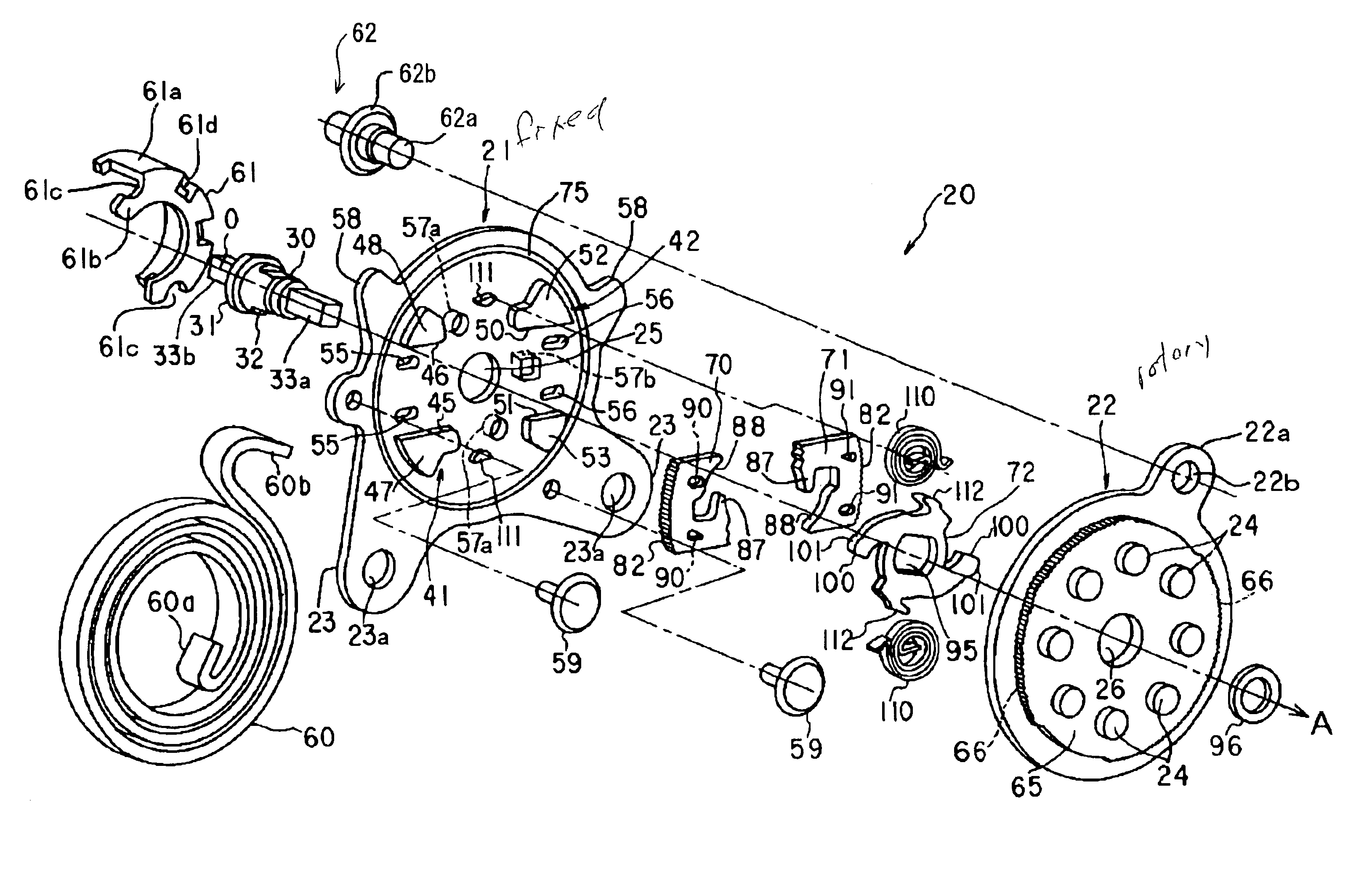
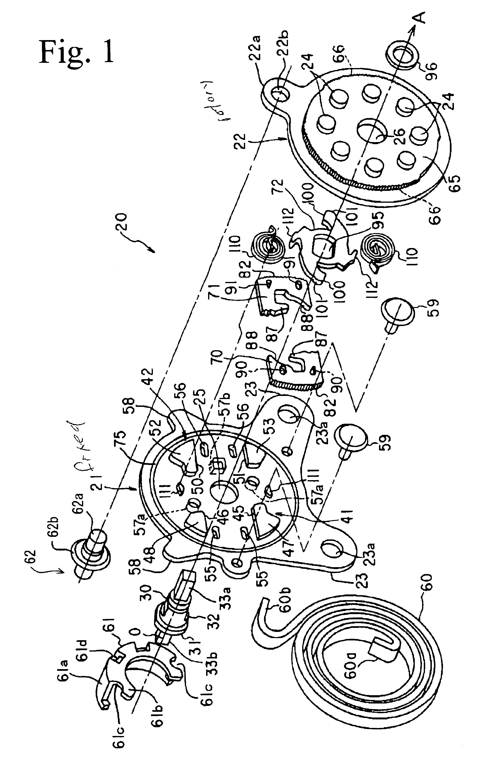
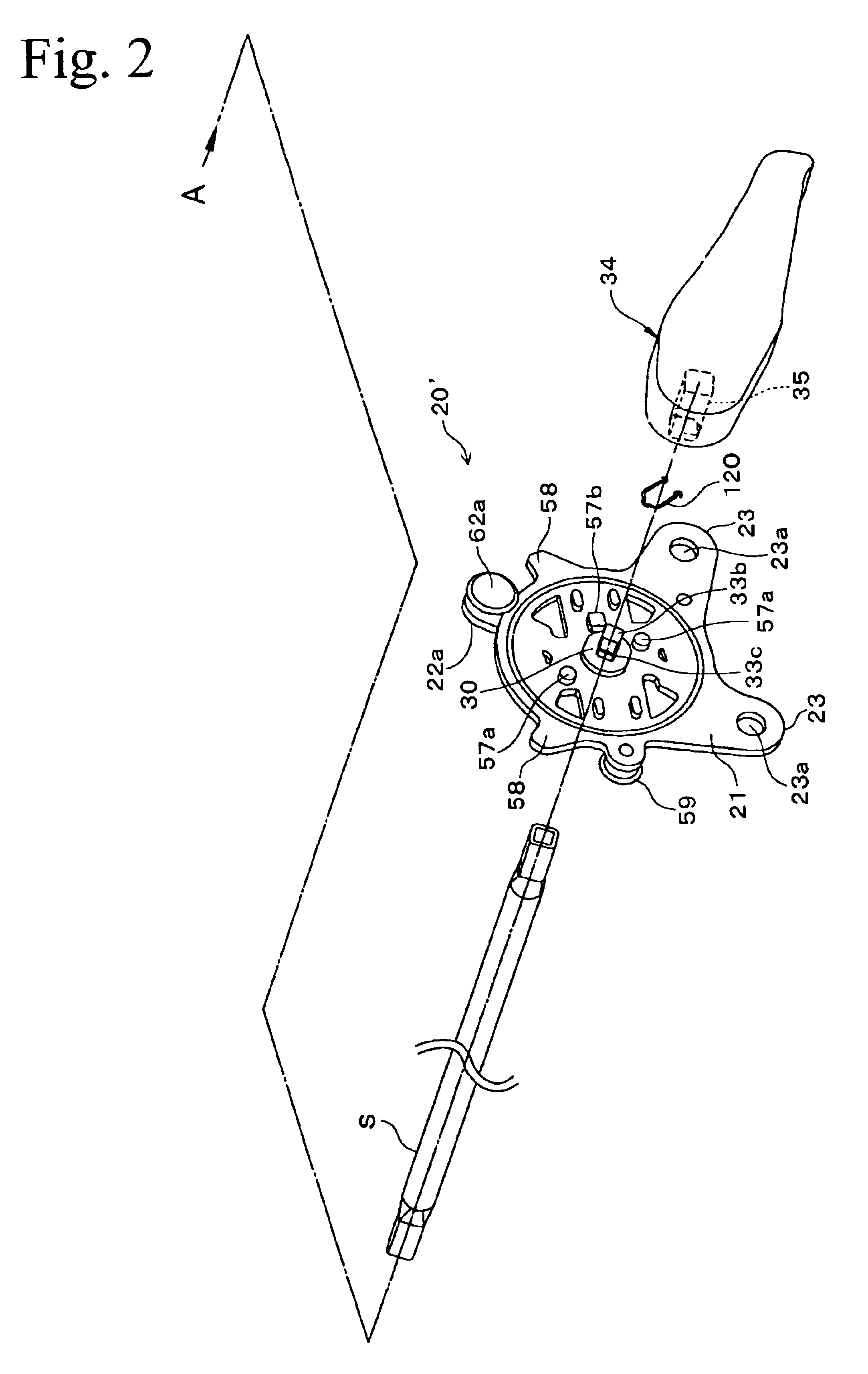
A description will be given of a second embodiment in accordance with the present invention with reference to FIGS. 1 to 4 and FIGS. 10 to 12. A reclining apparatus in accordance with the second embodiment has substantially the same structure as that of the first embodiment mentioned above, however, is different therefrom in the following points.

That is, a pair of round type positioning convex portions 57a and a pair of rectangular type positioning convex portions 57b which are protruded outward in accordance with a press molding are provided near the center through hole 25 of the fixed plate 21. The round type positioning convex portions 57a are arranged at positions symmetrical with each other with respect to the axis O, and the round type positioning convex portions 57a and the rectangular type positioning convex portions 57b are apart from the axis O with the same distance. Furthermore, the bracket 61 is fixed to the round type positioning convex portions 57a and the rectangular...

third embodiment

A description will be given of an embodiment in accordance with the present invention with reference to FIGS. 1 to 4 and FIGS. 10 to 13. A reclining apparatus in accordance with a third embodiment has substantially the same structure as that of the first embodiment mentioned above, however, is different therefrom in the following points.

That is, a reclining apparatus 20 (20′) in accordance with the third embodiment is arranged such that in a condition that the fixed plate 21 is fixed to a seat cushion S1, as shown in FIG. 13, one slide gear 71 is arranged forward and another slide gear 70 is arranged backward. In this case, the reclining apparatus 20 in FIG. 13 is illustrated by seeing through the slide gears 70 and 71 and the cam member 72. These slide gears 70 and 71 are arranged forward and backward so that a moving direction thereof is inclined in a slightly forward ascending direction, and a center of each of the gear teeth portions 82 engaging with the internal gear 66 vertica...

fourth embodiment

A description will be given of a fourth embodiment in accordance with the present invention with reference to FIGS. 14 to 17 and FIG. 4. A reclining apparatus in accordance with the fourth embodiment has L1 substantially the same structure as that of the first embodiment, however, is different therefrom in the following points.

Comparatively small flange portions 29 are formed at two predetermined portions of the outer peripheral portion in the fixed plate 21, and a holding member 59 for preventing the rotary plate 22 from breaking away from the fixed plate 21 is provided in the flange portions 29. The L1 holding member 59 has a flange 59b in one end of a pin 59a, the pin 59a is inserted to a hole 29a formed in the flange portion 29 so as to be fixed to the fixed plate 21, as shown in FIG. 4, thereby slidably holding the outer peripheral portion of the rotary plate 22 between the fixed plate 21 and the flange 59b.

On the contrary, a holding member 62 for preventing the rotary plate 2...


PUM


Abstract

A reclining apparatus (20) is provided with a fixed plate (21) having guide portions (41, 42), a shaft (30), a rotary plate (22) having an internal gear (66), slide gears (70, 71), a cam member (72) and the like. The cam member (72) has a pair of hook portions (100) engaging with a receiving portion (87) in the slide gears (70, 71). The hook portion (100) and the receiving portion (87) are formed in such a shape as to move the slide gears (70, 71) is a direction of canceling a rotational moment applied to the slide gears (70, 71) due to a backward load applied to the seat back when the cam member (72) rotates in a lock canceling direction. A supporting portion (120) preventing the slide gears (70, 71) from moving in a direction of the rotational moment is provided in an opposing portion between the cam member (72) and the slide gears (70, 71).

Description

TECHNICAL FIELDThe present invention relates to a reclining apparatus suitable for adjusting an angle of incline of a backrest, for example, in a seat for an automobile.BACKGROUND ARTVarious types exist in the reclining apparatus, for example, there has been suggested an internal gear type reclining apparatus as described in Japanese Patent Application Laid-Open No. 7-231820. The internal gear type reclining apparatus is, as one embodiment thereof is shown in FIG. 18, provided with a fixed plate 3 having a pair of guide convex portions 1 and 2 opposing to each other, a slide gear 4 received between the guide convex portions 1 and 2, a rotary plate 6 having an internal gear 5, a cam member 7 and the like. The cam member 7 can be rotated in a direction of an arrow A in FIG. 18 (a lock canceling direction) by an operating lever 8. The fixed plate 3 is fixed to a frame in a seat cushion side. The rotary plate 6 is fixed to a frame in a seat back side and can rotate around a shaft 9 inte...

Claims


Application Information

Patent Timeline
IPC IPC(8): B60N2/235
CPCB60N2/2356B60N2/236
Inventor MIYATA, KAKUJISASAKI, AKIRANONOMIYA, MASAAKIMINAGAWA, TOSHIKAZU
Owner NHK SPRING CO LTD
Why Eureka
Try Eureka