
Universal Framed Cofferdam

a cofferdam and universal frame technology, applied in the direction of caissons, towers, buildings, etc., can solve problems such as unsuitability, and achieve the effects of economic viability, simple production, and prevention of drift and erosion

Inactive Publication Date: 2010-09-16
FEYGIN VITAL BORIS +1
View PDF7 Cites 29 Cited by
  • Summary
  • Abstract
  • Description
  • Claims
  • Application Information

AI Technical Summary

Benefits of technology

[0015]Another, primary objective of the present invention is to create a self floating structure that can be built in the convenience of the Dry Dock and than floated to the site of construction.
[0016]A further object of the present invention is to create a space frame that can effectively engage force of the barge impact or force coming from the Mooring device by using mechanisms provided by both conventional Cellular Cofferdam structure and Columnar structure of the Dolphin.
[0022]Objective of that invention is to use preloaded anchor devices for additional Cofferdam stability and prevention of drift and erosion of Cellular Cofferdam granular fill. (FIG. D1; FIG. D2; FIG. D3)
[0023]And still further objective of the present invention is to provide a composite Cellular Cofferdam that is economically viable and simple in production.
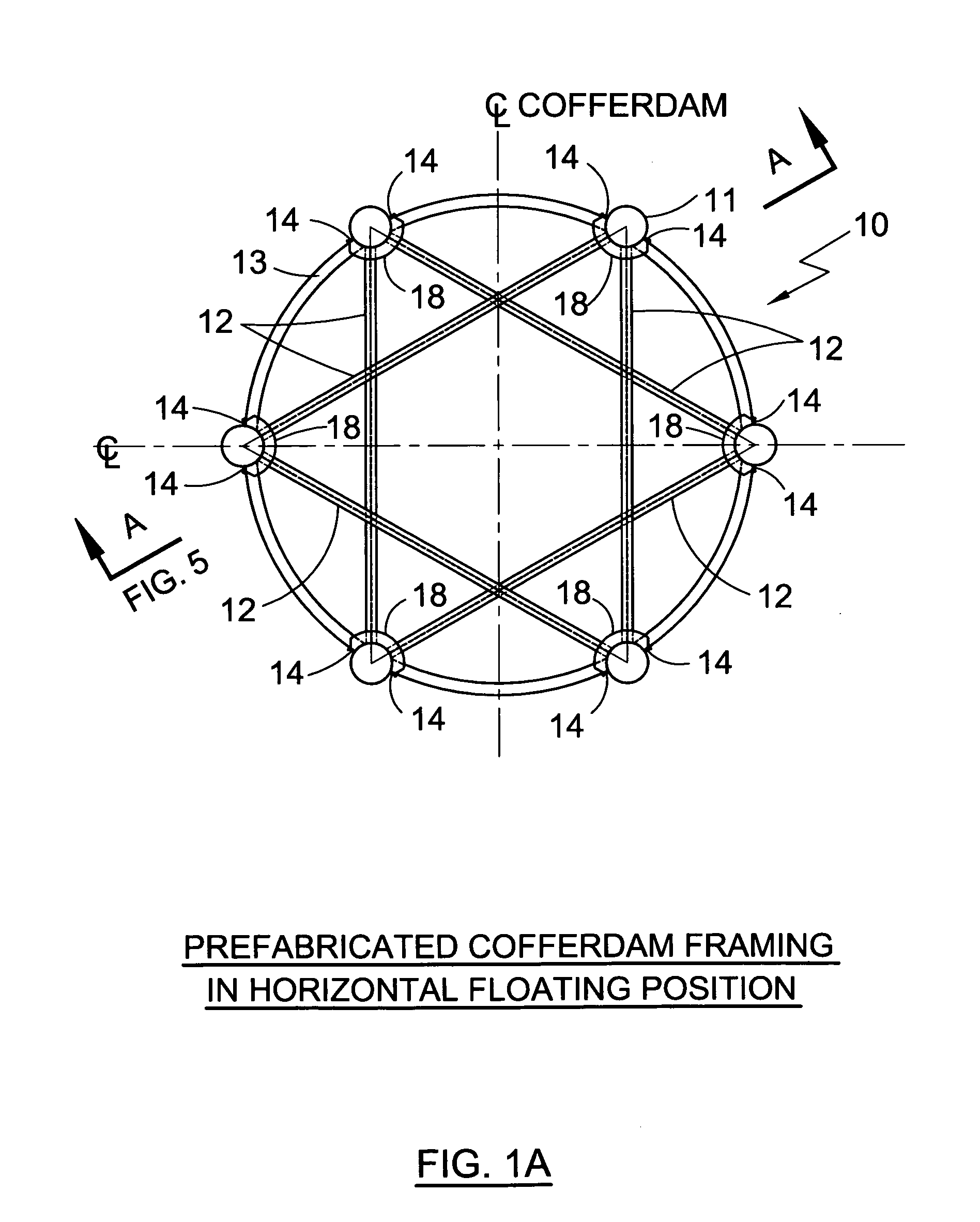
[0028]the rock sockets predrilled for Rock Anchor installation. Prefabricated framing also allows easy transportation of the Cofferdam from the manufacturing facility to the site of construction. It allows ease of installation of the sheet pile skin in the river environment where high speed currents can affect sheet pile installation.The framing of the Universal Cofferdam is manufactured in the convenience of the Dry Dock where each end of the pipe column is sealed (FIG. 3&FIG. 4). After completion of the frame fabrication Dry Dock is flooded, Cofferdam framing brought into horizontal position (FIG. 1A) and floated from the Dry Dock facility to the site of construction where seal is removed from the pipe ends and Cofferdam framing is brought into vertical position with the help of floating cranes. Finally, Cofferdam framing is lowered into position until it firmly touches the river or sea bed in a perfectly vertical position (FIG. 5). Jetting through the river silt can be utilized to aid that process. In the next step rock sockets are drilled through the vertical pipe annular spaces and rock anchors installed. In the following steps flat sheet pile skin of the Universal Framed Cofferdam is installed and Cofferdam is filled with compacted gravel. That concludes the process of cofferdam construction.

Problems solved by technology

While present day Cellular Cofferdams are well suitable for the purposes for which they were designed, they would not be suitable for the purposes of present invention where magnitude of the lateral load far exceeds the load level that conventional Cellular Cofferdams were designed for.

Method used


Image

  • Universal Framed Cofferdam
  • Universal Framed Cofferdam
  • Universal Framed Cofferdam

Examples


Embodiment Construction

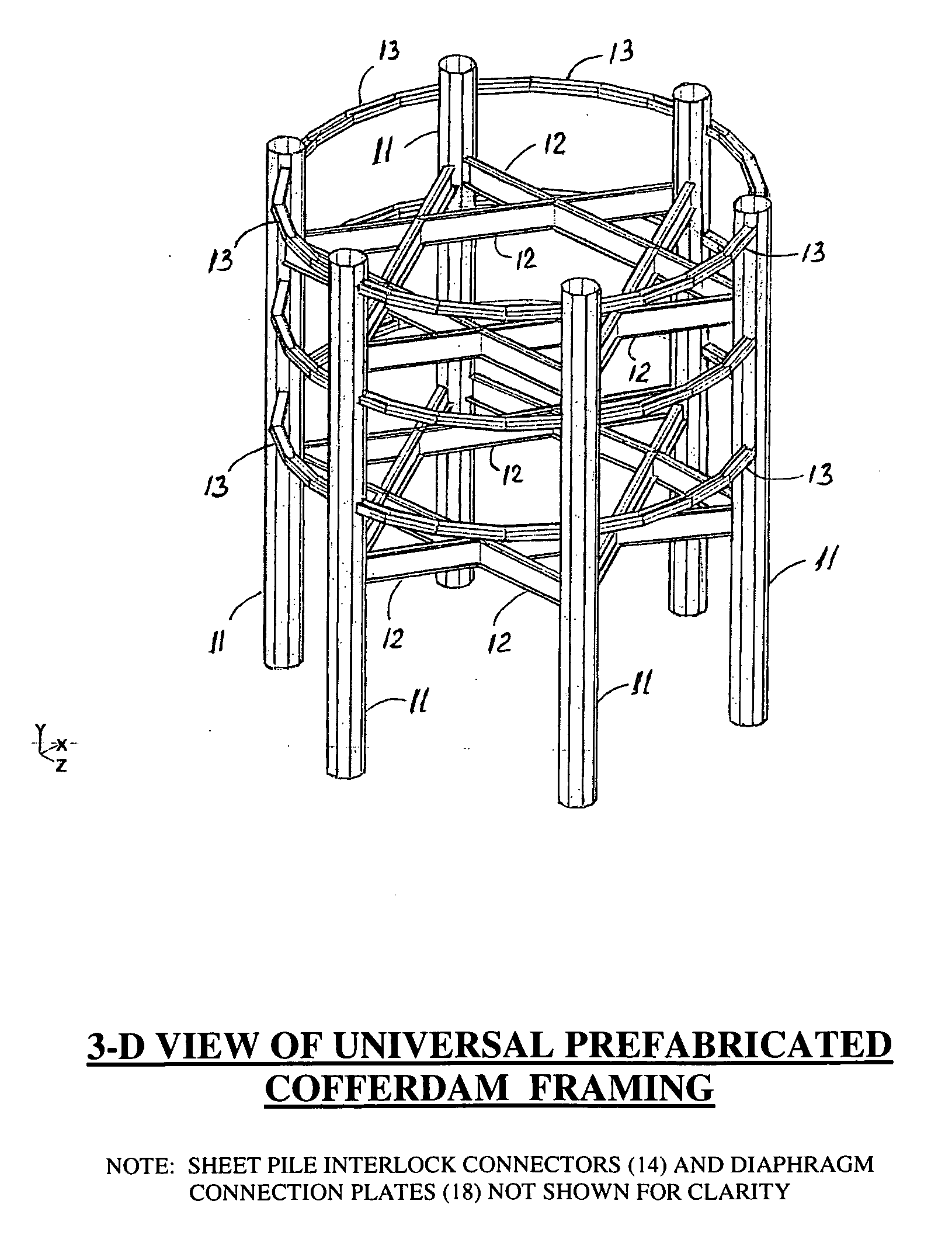
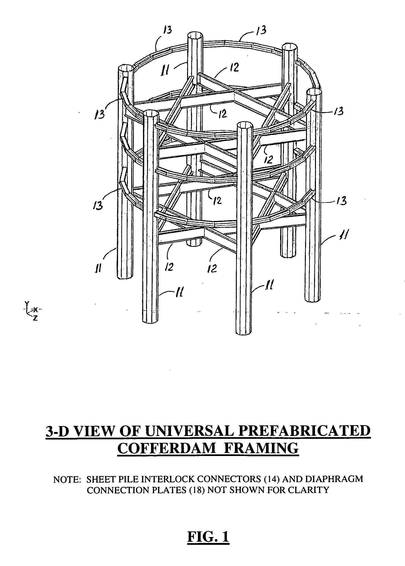
[0063]The present invention relates to an improved method of construction and installation of sheet pile Cellular Cofferdams. It also relates to improved design of Cofferdam structure itself, creating a new subclass that can be called Columnar Cofferdam structure. The following discussion describes in detail one embodiment of invention. This discussion, however, should not be construed, as limiting the invention to this particular embodiment. Practitioners skilled in the art will recognize other numerous embodiments as well. The drawings show similar elements of the invention denoted by the same numerical character in all views and sections shown in FIG. 1 through FIG. 9 where the present invention generally depicted by the numeral 10.

[0064]FIG. 1 is a 3-D View of Universal Prefabricated Cofferdam Framing.

[0065]FIG. 1A is an illustrative view of the prefabricated Cofferdam framing in a floating position. The prefabricated Cofferdam framing 10 includes six pipe columns 11 with liftin...


PUM


Abstract

Universal Framed Cofferdam has prefabricated skeletal steel space framing formed from multiple steel vertical pipes and two levels of horizontal diaphragm trusses rigidly connected to pipe columns. Beams of each diaphragm truss are attached to vertical pipes of the framing with rigid moment connections creating a rigid space frame of the perfectly round form that is used as a false work of the Cofferdam. Wales of the Cofferdam and short pieces of the flat sheet piling are attached to the vertical pipes forming a skeleton of the Cellular structure. The Skeleton of the Universal Framed Cofferdam is prefabricated in the convenience of the Dry Dock and than floated to the site. Buoyancy of the framing allows Cofferdam skeleton transportation without using the barge or otherwise necessary floating devices. Once brought to the site of installation Cofferdam skeleton is installed vertically in position and leveled on the bottom of the river bed. If necessary river silt can be jetted and pumped out of pipe annular space and pipe columns of framing can be simultaneously lowered in position by using vibro—hummer. After space framing installation, rock sockets are predrilled through the annular space of vertical pipes and rock anchors installed. Sheet pile skin of the Cofferdam installed between pipe columns concludes Cofferdam Can erection. Universal Framed Cofferdam Can than filled with compacted gravel and becomes a Hybrid Gravity Caisson / Columnar water front or marine structure that has the best features of the Conventional Cellular Cofferdam and of Columnar Dolphin structure. It has enhanced sliding and overturning stability provided by Rock anchors preloaded by Cofferdam granular fill and has effective mechanism that prevents concave or convex surface of rupture failure that may be suffered by conventional Cellular Cofferdams, and has mechanism that more effectively resists deep surface sliding failure of the Cofferdam base.

Description

BACKGROUND OF THE INVENTION[0001]1. Field of the Invention[0002]The present invention is a hybrid of Cellular Cofferdam and of Columnar Dolphin structure. More specifically, it is a prefabricated Columnar structure that is floated to the site and built as Rock Anchored gravel filled Cellular Cofferdam structure after on site installation of perimeter sheet pile skin.That type of structure can be utilized for many types of waterfront projects like:[0003]Mooring or Breasting Dolphins[0004]Quay Wall And most notably[0005]Bridge Pier Fender system where extremely high lateral load application from the Ship Collision impact makes open Columnar Fender Structure or conventional Cellular Cofferdam construction unviable and / or uneconomical solution.[0006]2. Description of the Prior Art[0007]Numerous structures that were designed for similar tasks include Pile supported Dolphins, Open (Pile supported) or Closed (Cellular Cofferdam) Marginal Wharfs.[0008]While benefits of present invention wer...

Claims


Application Information

Patent Timeline
IPC IPC(8): E02D19/04E02D25/00E04H12/00
CPCE02D19/04
Inventor FEYGIN, VITALY BORISZASLAVSKY, MARGARET
Owner FEYGIN VITAL BORIS
Learn More