
Lid Body and Pressure Cooker

a lid body and pressure cooker technology, applied in the field of lids, can solve the problems of product inability to operate normally, air leakage, and bulging at the circumference of the surface of the top lid, and achieve the effects of reducing the clearance between the top lid and the pot lid, improving product quality, and reducing exhaustion

Active Publication Date: 2021-03-11
FOSHAN SHUNDE MIDEA ELECTRICAL HEATING APPLIANCES MFG CO LTD
View PDF0 Cites 6 Cited by
  • Summary
  • Abstract
  • Description
  • Claims
  • Application Information

AI Technical Summary

Benefits of technology

The present invention aims to provide a lid body that is small in size and can prevent air leakage from the solenoid exhaust valve. This design achieves this by eliminating a portion of the top lid, shortening the distance between the valve cover and the valve seat, improving the valve cover attraction and repulsion effect of the magnetic field generated in the solenoid coil, and reducing the number of windings of the coil. This leads to a decrease in the dimensions of the valve seat and overall product, enhances the esthetic appearance of the product, and increases competitiveness of the product.

Problems solved by technology

With that structure, since the top lid is always tensioned by the exhaust valve core and the contact area between the exhaust valve core and the top lid is small, the fitting surface of the top lid where the exhaust valve core is fitted will deform after long-time operation of the product, resulting in bulging at the circumference of the surface of the top lid in contact with the exhaust valve core.
Consequently, air leakage from the solenoid exhaust valve may occur, and the product cannot operate normally.

Method used


Image

  • Lid Body and Pressure Cooker
  • Lid Body and Pressure Cooker
  • Lid Body and Pressure Cooker

Examples


Embodiment Construction

[0050]To make the above-mentioned object, features and advantages of the present invention understood more clearly, hereunder the present invention will be further described in detail in connection with drawings and embodiments. It should be noted that the embodiments and the features in the embodiments of the present application may be combined with each other, if there is no conflict among them.

[0051]Although many details are described in the following to facilitate fully understanding the present invention, the present invention may be implemented in other manners besides the manner described here. Therefore, the scope of protection of the present invention is not limited to the specific embodiments disclosed hereunder.

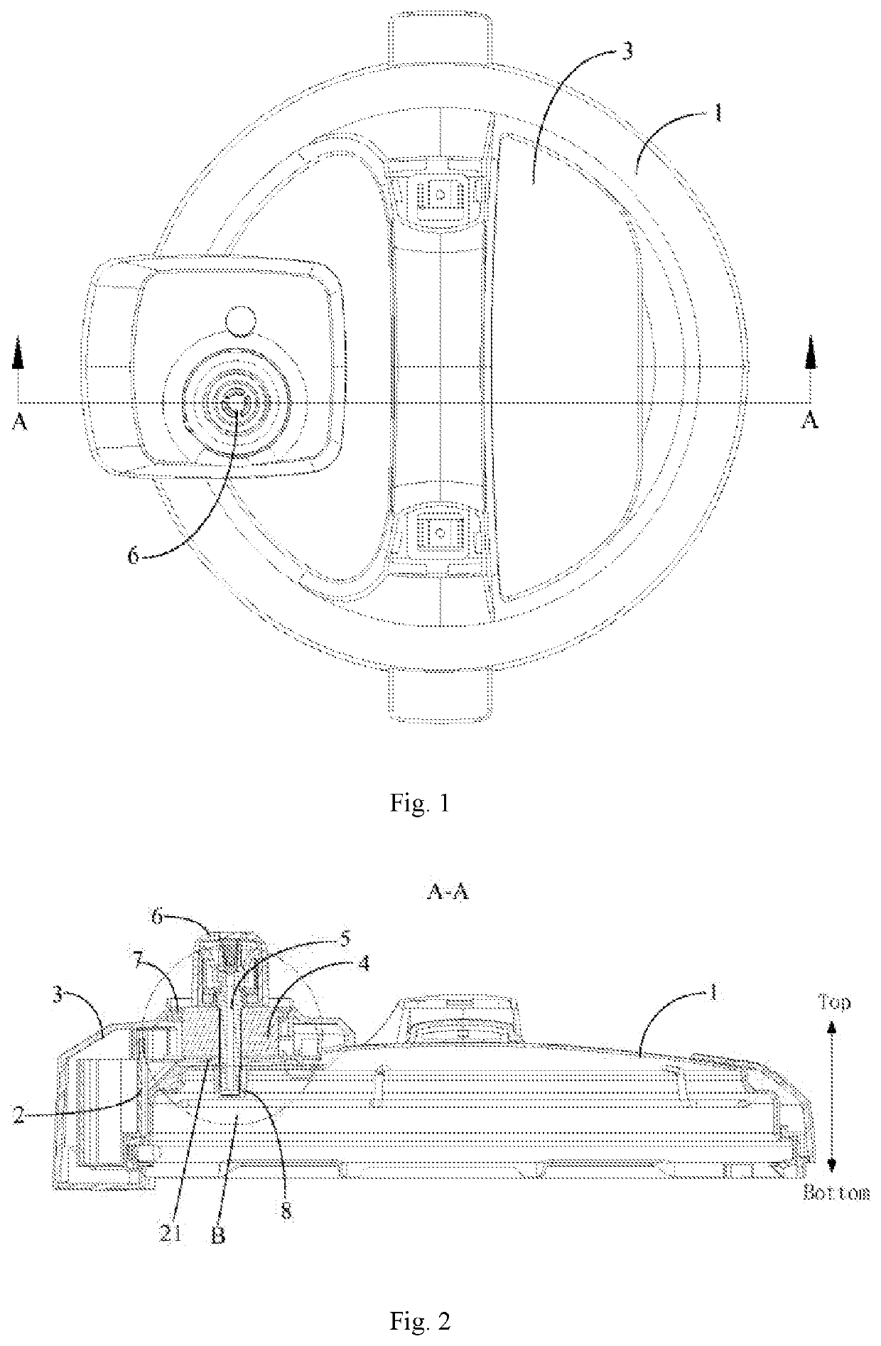
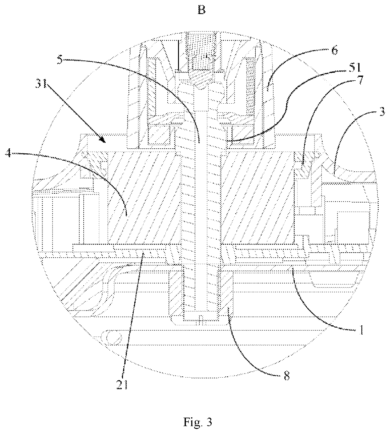
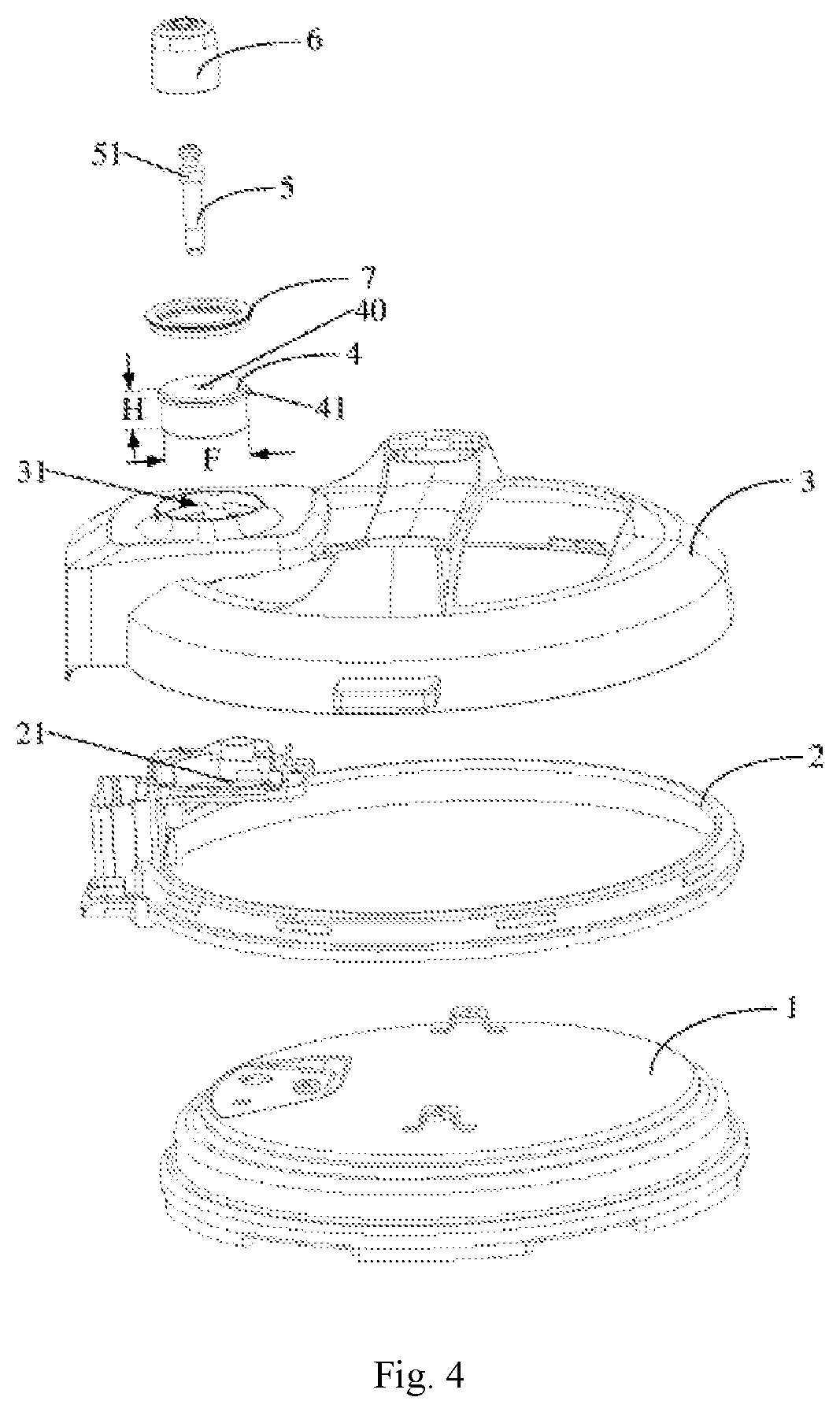
[0052]As shown in FIGS. 1-11, in the first aspect of the present invention, an embodiment provides a lid body for a pressure cooker. The lid body comprises a pot lid 1, an inner lid 2, a top lid 3 and a solenoid exhaust valve, wherein the inner lid 2 is mounted at ...


PUM


Abstract

A lid body for a pressure cooker includes a pot lid, an inner lid mounted at an outer side of the pot lid, a top lid mounted at an outer side of the inner lid, and a solenoid exhaust valve. The pot lid includes a mounting cavity and a limiting rib protruding inward from a side wall of the mounting cavity. The solenoid exhaust valve includes a valve seat mounted in the mounting cavity and including a mounting hole, a valve core inserted in the mounting hole, and a valve cover matingly connected with a top of the valve core and being movable with respect to the valve core. A bottom end of the valve seat abuts against an upper end face of the limiting rib, and a lower end face of the limiting rib abuts against the pot lid or the inner lid.

Description

TECHNICAL FIELD[0001]The present invention relates to the field of cookers, in particular to a lid body and a pressure cooker having the lid body.BACKGROUND TECHNOLOGY[0002]Existing pressure cookers employ a solenoid exhaust valve for automatic exhaustion. These products change the magnitude and / or direction of the current in the coil in the solenoid valve seat by means of circuit control, so as to change the magnitude or direction of the magnetic field generated by the solenoid valve seat to realize attraction and repulsion to the solenoid valve and thereby control the open or close of the solenoid exhaust valve.[0003]To prevent the fit clearance between the top lid and the pot lid from exceeding standard, such products employ the following structure: an inner lid is arranged between the pot lid and the top lid, the solenoid valve seat is fixed on the inner lid and after which the top lid is snap-fitted, then the exhaust valve core is inserted from the top through the top lid first...

Claims


Application Information

Patent Timeline
Patent Type & Authority Applications(United States)
IPC IPC(8): A47J27/092
CPCA47J27/092A47J27/08
Inventor PENG, FENG
Owner FOSHAN SHUNDE MIDEA ELECTRICAL HEATING APPLIANCES MFG CO LTD
Learn More