Abnormality diagnosis system and abnormality diagnosis method

a diagnostic system and abnormality technology, applied in the field of abnormality diagnosis system, can solve problems such as failure, and achieve the effect of detecting abnormalities quickly and appropriately

Inactive Publication Date: 2021-03-11
HITACHI ASTEMO LTD
View PDF3 Cites 20 Cited by
  • Summary
  • Abstract
  • Description
  • Claims
  • Application Information

AI Technical Summary

Benefits of technology

[0009]According to the present invention, there is provided a technology capable of easily and appropriately diagnosing an abnormality related to control of automatic driving of a vehicle.

Problems solved by technology

When the calculation results of the operation amounts of the main ECU and the sub ECU do not match, it is determined that a failure occurs.

Method used


Image

  • Abnormality diagnosis system and abnormality diagnosis method
  • Abnormality diagnosis system and abnormality diagnosis method
  • Abnormality diagnosis system and abnormality diagnosis method

Examples


first embodiment

[0036]First, a first embodiment will be described.

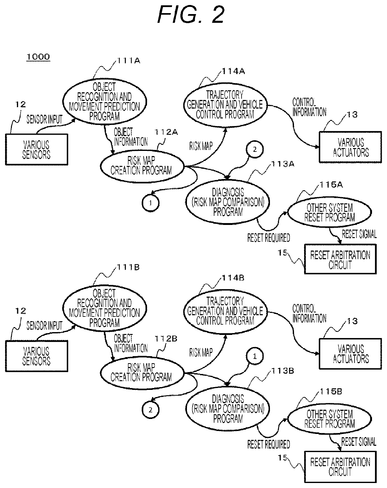
[0037]FIG. 1 is an overall configuration diagram of a vehicle control system according to the first embodiment.

[0038]A vehicle control system 1000 as an example of an abnormality diagnosis system is a system mounted on a vehicle such as an automobile, and includes various sensors 12, various actuators 13, a plurality of electronic control units (ECUs) 1A and 1B, and a reset arbitration circuit 15. The ECU 1A and the ECU 1B are connected to communicate with each other via an in-vehicle network 14. The in-vehicle network 14 may be any communication network such as Ethernet (registered trademark) and CAN-FD (CAN with Flexible Data-Rate).

[0039]The various sensors 12, the various actuators 13, and the reset arbitration circuit 15 are connected to the ECUs (1A and 1B).

[0040]The various sensors 12 include one or more sensors such as a radar, a camera, and a GPS sensor for obtaining information on a surrounding environment of the vehicle. Th...

second embodiment

[0085]Next, a second embodiment will be described.

[0086]FIG. 7 is an overall configuration diagram of a vehicle control system according to the second embodiment.

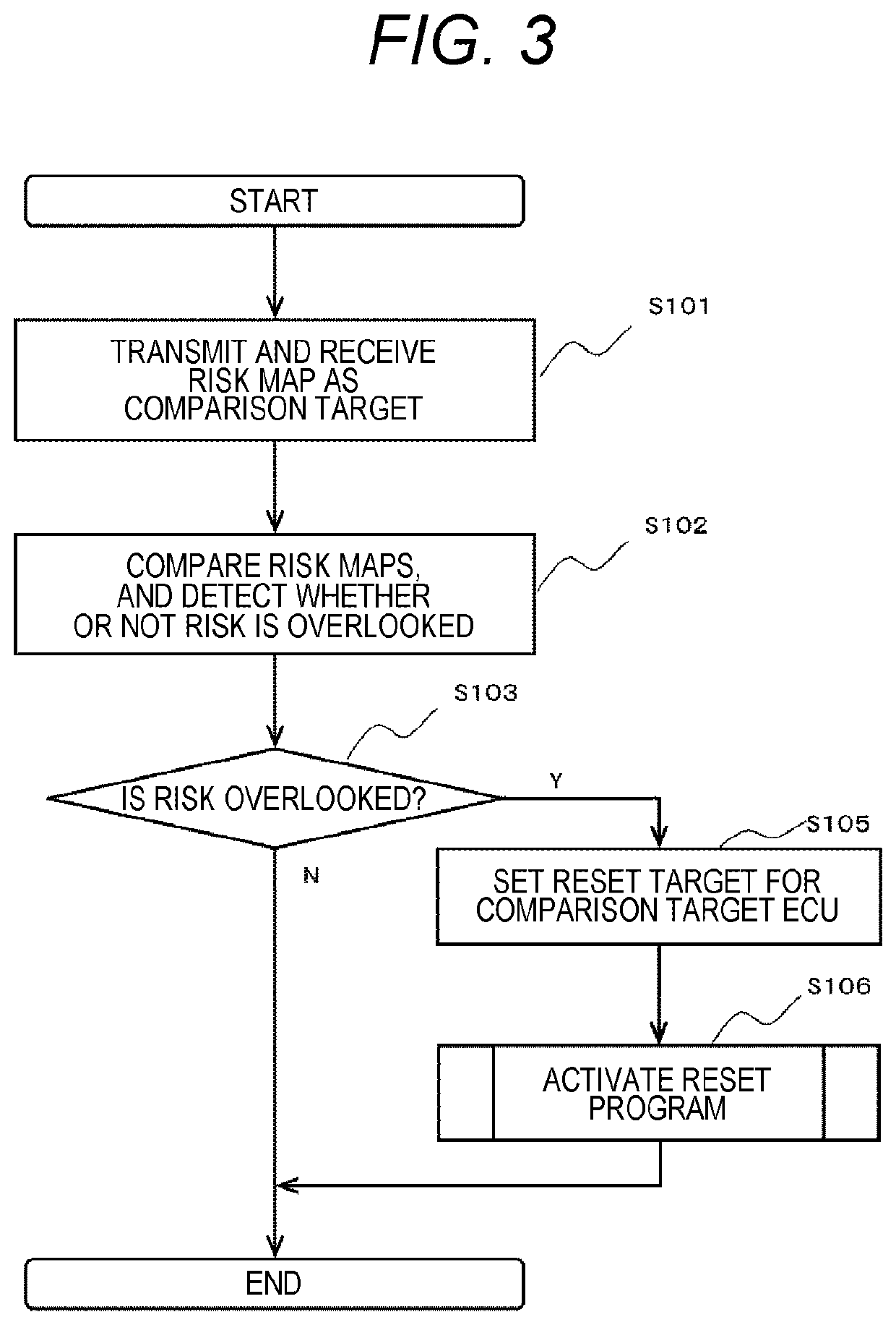
[0087]A vehicle control system 1001 according to the second embodiment is a system different from the vehicle control system 1000 according to the first embodiment in that the memory (11A, 11B) further includes a transmission risk map (117A, 117B: an example of a partial risk map), a risk map comparison condition (static) (118A, 118B), and a risk map extraction program (119A, 119B) are stored. Here, a functional unit constituted by the CPU (10A, 10B) that executes the risk map extraction program (119A, 119B) is an example of an extraction unit.

[0088]The transmission risk map (117A, 117B) is a risk map transmitted according to the risk map transmission request from the other ECU, and is partial information (a set of combinations of coordinates and risk levels corresponding to these coordinates for partial coordinates of the ...

third embodiment

[0100]Next, a third embodiment will be described.

[0101]FIG. 10 is an overall configuration diagram of a vehicle control system according to the third embodiment.

[0102]A vehicle control system 1002 according to the third embodiment is a system different from the vehicle control system 1001 according to the second embodiment in that risk map comparison conditions (static and dynamic) (140A, 140B) are provided instead of the risk map comparison conditions (static) (118A, 118B), transmission risk maps (with history) (141A, 141B) are provided instead of the transmission risk maps (117A, 117B), and risk map extraction programs (142A, 142B) are provided instead of the risk map extraction programs (119A, 119B).

[0103]The risk map comparison condition (static and dynamic) (140A, 140B) is a condition for extracting the transmission risk map (with history) (141A, 142B) from the risk map (116A, 116B). The risk map comparison condition (static and dynamic) (140A, 140B) includes the same condition...


PUM


Abstract

An abnormality related to control of automatic driving of a vehicle can be easily and appropriately diagnosed. In a vehicle control system 1000, a plurality of risk information generation units (CPUs 10A and 10B that execute risk map creation program 112A and 112B) that generates risk map which is used for automatic driving control of a vehicle when the vehicle moves based on sensor information related to an object around the vehicle is provided. Diagnosis units (CPUs 10A and 10B that execute diagnosis (risk map comparison) programs 113A and 113B)) that diagnose whether or not an abnormality occurs in the generated risk information based on a plurality pieces of risk information generated by the plurality of risk information generation units is provided.

Description

TECHNICAL FIELD[0001]The present invention relates to an abnormality diagnosis system that diagnoses an abnormality related to control of automatic driving of a vehicle.BACKGROUND ART[0002]In recent years, electronic control units (ECUs) for automatic driving have been developed in order to perform automatic driving of a vehicle. For example, as a diagnosis method of diagnosing an abnormality of the ECU for automatic driving, there is a method described in PTL 1. In the method described in PTL 1, a main ECU and a sub ECU each include a calculation unit and a failure detection unit, and the failure detection unit monitors a result of an operation amount calculated by the calculation unit. The failure detection unit monitors the amount of changes in the operation amount of the calculation result, and determines that the ECU fails when the amount of changes exceeds a predetermined range. When the calculation results of the operation amounts of the main ECU and the sub ECU do not match,...

Claims


Application Information

Patent Timeline
Patent Type & Authority Applications(United States)
IPC IPC(8): B60W60/00G07C5/08B60W50/00
CPCB60W60/0016B60W50/0098G07C5/0808B60W50/04B60W50/045B60W50/0205B60W2050/0215B60W40/02B60W60/0015
Inventor SERIZAWA, KAZUYOSHIEBINA, TOMOHITONARISAWA, FUMIO
Owner HITACHI ASTEMO LTD
Why Eureka
Try Eureka