Video transmitting device, video transmitting method, and recording medium

a video and transmission device technology, applied in the field of video transmission devices, can solve the problems of insufficient, waste, and inability of the technique to take into account any waste of network band between the vehicle and the remote monitoring system, and achieve the effect of reducing waste of network band

Active Publication Date: 2020-03-12
PANASONIC INTELLECTUAL PROPERTY CORP OF AMERICA
View PDF9 Cites 9 Cited by
  • Summary
  • Abstract
  • Description
  • Claims
  • Application Information

AI Technical Summary

Benefits of technology

[0013]The video transmitting device, the video transmitting method, and the recording me

Problems solved by technology

According to Japanese Patent No. 5366703, although the operator can check images captured by the camera in the vehicle, the technique fails to take into cons

Method used


Image

  • Video transmitting device, video transmitting method, and recording medium
  • Video transmitting device, video transmitting method, and recording medium
  • Video transmitting device, video transmitting method, and recording medium

Examples


embodiment 1

[0068]A video transmitting device and so on according to the present embodiment will be described below with reference to FIGS. 1 to 9B.

[1−1. Configuration of Vehicle Controlling System]

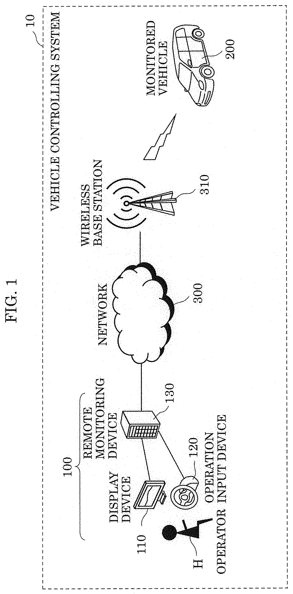
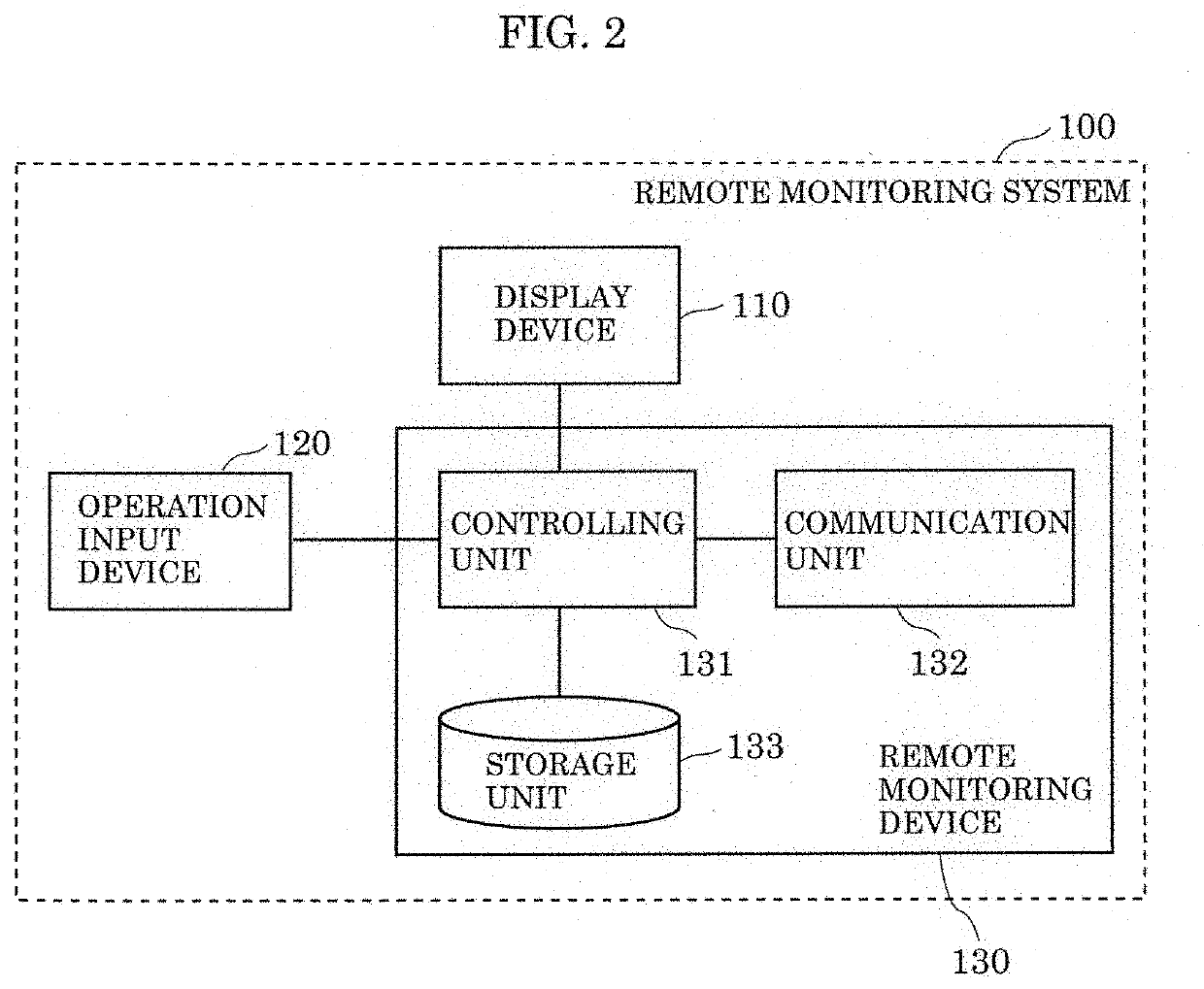
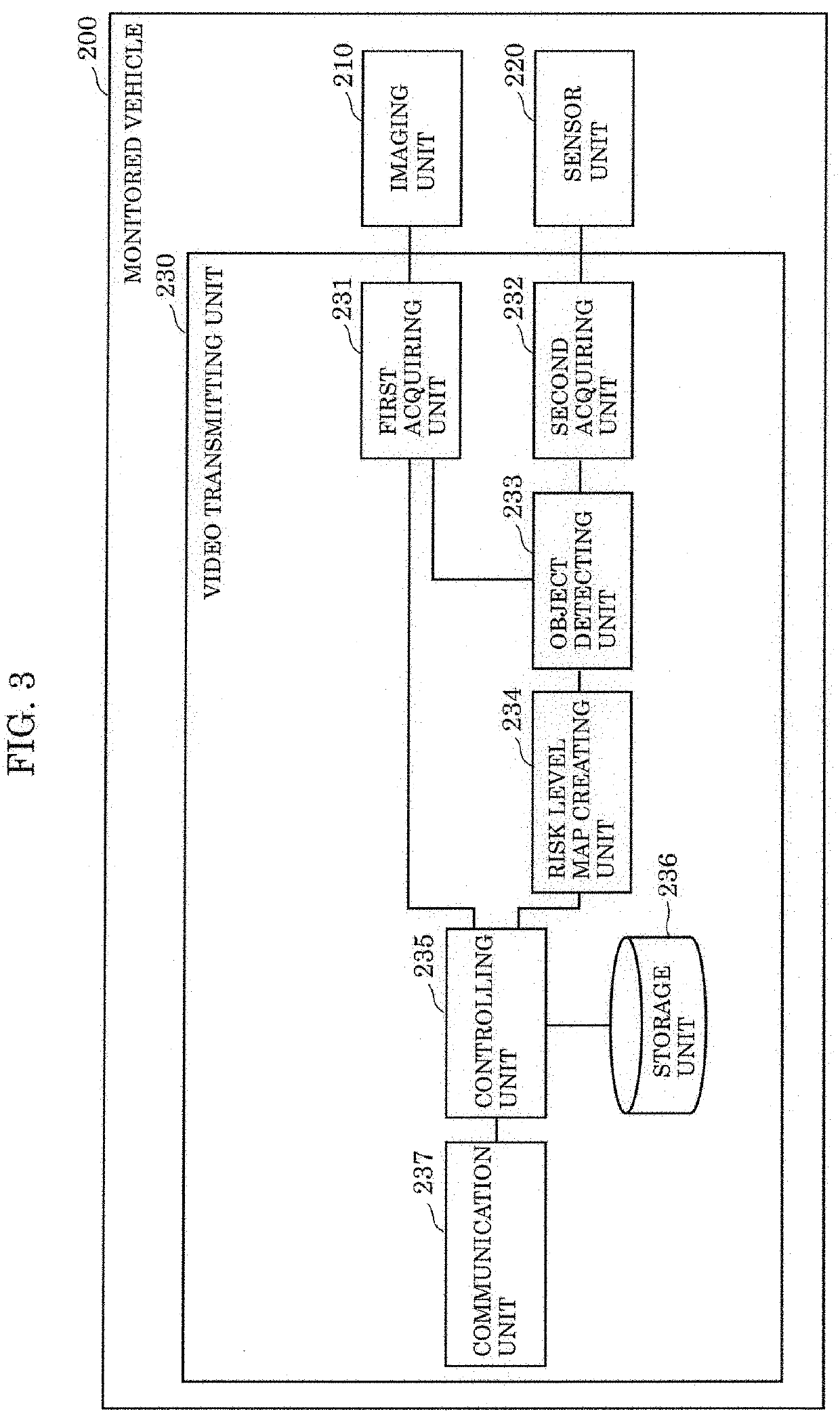
[0069]A configuration of a vehicle controlling system including a monitored vehicle provided with a video transmitting device according to the present embodiment will be described first with reference to FIGS. 1 to 3. FIG. 1 illustrates a schematic configuration of vehicle controlling system 10 according to the present embodiment.

[0070]As illustrated in FIG. 1, vehicle controlling system 10 communicably connects monitored vehicle 200 and remote monitoring system 100 (specifically, remote monitoring device 130) via network 300 and wireless base station 310 for a wireless LAN, a communication terminal, or the like. Wireless base station 310 and network 300 are examples of a communication network. Monitored vehicle 200 is an example of a vehicle that operator H at least remotely monitors. Monitored vehi...

embodiment 2

Variation 2 of Embodiment 2

[0197]A video transmitting device and so on according to the present variation will be described below with reference to FIG. 15. A monitored vehicle provided with the video transmitting device according to the present variation has a configuration similar to that in Variation 1, and thus descriptions thereof will be omitted. FIG. 15 is a flowchart illustrating an operation of video transmitting device 230a according to the present variation. Processes in steps S610 to S670 illustrated in FIG. 15 are similar to the processes in steps S510 to S570 illustrated in FIG. 14, and thus descriptions thereof will be omitted.

[0198]If NW status monitoring unit 238 has determined that the NW is not congested (No in S670), controlling unit 235 creates the second video information to be transmitted to remote monitoring device 130. The second video information created when the result is No in step S670 has a data amount greater than the data amount of the second video in...


PUM


Abstract

A video transmitting device is to be provided in a vehicle and includes a first acquiring unit that acquires first video information from an imaging unit that captures images of the surroundings of the vehicle, a risk map creating unit that creates a risk map indicating a risk region in traveling of the vehicle, a video creating unit that creates second video information having a data amount smaller than a data amount of the first video information on the basis of the risk map, and a communication unit that transmits the second video information to a remote monitoring device for remotely monitoring the vehicle.

Description

CROSS REFERENCE TO RELATED APPLICATION[0001]This application claims the benefit of priority of Japanese Patent Application Number 2018-168948 filed on Sep. 10, 2018, and 2019-084992 filed on Apr. 26, 2019, the entire contents of which are hereby incorporated by reference.BACKGROUND1. Technical Field[0002]The present disclosure relates to video transmitting devices to be provided in vehicles, video transmitting methods, and recording medium.2. Description of the Related Art[0003]In one existing vehicle controlling system, a remotely located operator indirectly drives and / or operates a driverless vehicle or a vehicle that is not operated by a driver through wireless communication via a wireless local area network (LAN), a mobile phone circuit, or the like.[0004]In such a vehicle controlling system, via a communication network, a vehicle transmits, to the operator, sensing results obtained with in-vehicle sensors (e.g., millimeter-wave radar, laser radar, and camera) observing the vehi...

Claims


Application Information

Patent Timeline
IPC IPC(8): H04N7/18H04N5/262
CPCH04N7/183H04N5/2628H04N7/18H04L67/025H04L67/12G08G1/0104G08G1/04G08G1/0962G08G1/161H04N23/80H04N21/442H04N21/647H04J3/0667G08G1/0112G08G1/0133G08G1/096811G08G1/096844G06V20/56
Inventor SHIMOTSUMA, YUTAYONEDA, TAKAHIROISHII, YASUNORI
Owner PANASONIC INTELLECTUAL PROPERTY CORP OF AMERICA
Why Eureka
Try Eureka