System and method for creating orthogonal solder interconnects

a technology of orthogonal solder interconnection and soldering, which is applied in the direction of soldering apparatus, manufacturing tools, auxiliary welding devices, etc., can solve problems such as faulty or failed solder joints

Pending Publication Date: 2021-03-11
RAYTHEON CO
View PDF4 Cites 2 Cited by
  • Summary
  • Abstract
  • Description
  • Claims
  • Application Information

AI Technical Summary

Problems solved by technology

First, it applies mechanical pressure to maintain physical contact between the circuit board and the component contact.
Second, it applies heat to the area around the solder pad to melt the solder such that it “reflows” around the associated conductive pad of the circuit board and the contact of the component.
For example, after the solder tip is removed but before the solder has solidified, because the circuit board and component contact are no longer being physically held together, they may move relative to each other or even completely separate, which can result in a faulty or failed solder joint.

Method used


Image

  • System and method for creating orthogonal solder interconnects
  • System and method for creating orthogonal solder interconnects
  • System and method for creating orthogonal solder interconnects

Examples


Embodiment Construction

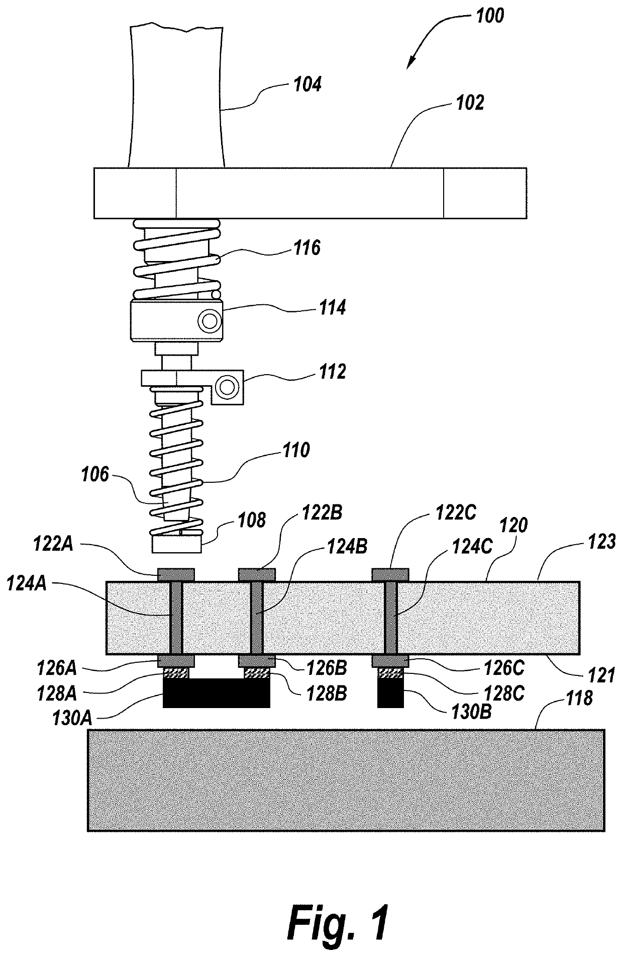
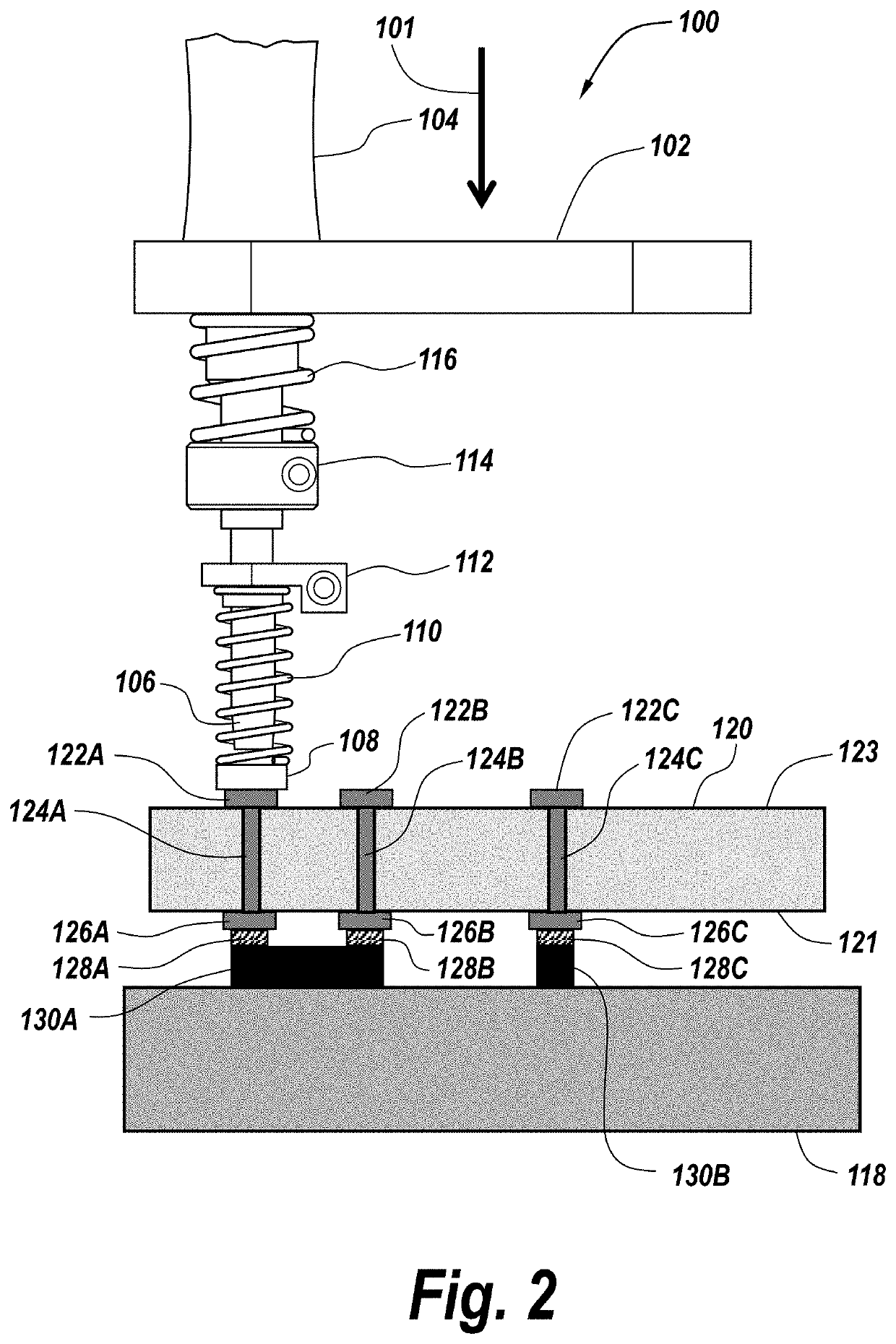
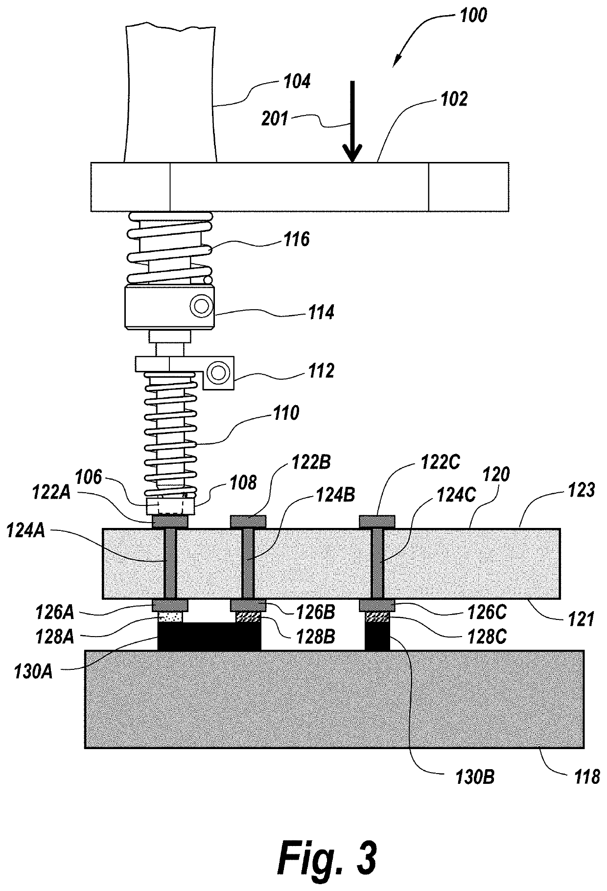
[0014]According to the present disclosure, a system and method for providing an orthogonal interconnect on the underside of a circuit board is provided. The solder tip itself utilizes a spring to keep the circuit board and component assembly under compression during the solder solidification phase and keeps the assembly planar. This is in contrast to typical conventional soldering robots, which use a standard solder tip in addition to a solder feeder. In these conventional systems, there is no compression after the solder is reflowed since, typically, the joint to be made is on the same side of the assembly as the solder tip.

[0015]According to the present disclosure, a solder tip assembly is configured to reflow a solder joint on the underside of a circuit board, while allowing the joint to cool under compression. This is especially useful when mating two interfaces together and preventing them from opening back up while the solder cools back to the solid state. The configuration of...


PUM

PropertyMeasurementUnit
forceaaaaaaaaaa
compression forceaaaaaaaaaa
forcesaaaaaaaaaa

Abstract

An apparatus and method for soldering an electrical component to a circuit board includes a stage positioning the circuit board and electrical component in alignment with a solder tip along an axis. A first spring-loaded compression mechanism maintains contact between the circuit board and the electrical component, and a second spring-loaded compression mechanism brings the soldering tip into thermal contact with the circuit board and the electrical component such that solder disposed adjacent to the circuit board and the electrical component melts. When the second spring-loaded compression mechanism removes its applied force such that the soldering tip comes out of contact with the circuit board, the first spring-loaded compression mechanism maintains the contact between the circuit board and the electrical component while the solder cools and solidifies.

Description

BACKGROUND1. Technical Field[0001]The present disclosure is related to assembly of circuit boards and, in particular, to systems and methods for soldering components to circuit boards usable with robotic positioning and soldering systems.2. Discussion of Related Art[0002]In robotic assembly of a circuit board, the circuit board, which includes a pattern of previously formed solder pads, is typically supported in a movable stage, with a solder tip located vertically above the circuit board and movable stage. A component to be fixedly mounted on the circuit board is positioned such that at least one of its conductive contact pads, leads or pins is in close proximity to or in contact with one of the solder pads on the circuit board. To attach the component contact to the circuit board, the stage, and, therefore, the circuit board, is controlled to move such that the associated circuit board solder pad is located directly under the solder tip. Next, the solder tip is activated to produc...

Claims


Application Information

Patent Timeline
Patent Type & Authority Applications(United States)
IPC IPC(8): H05K3/34B23K1/00B23K37/04
CPCH05K3/3494H05K1/0206B23K37/0426B23K1/0016B23K3/04B23K3/08B23K3/087B23K2101/42H05K3/0008H05K2203/0278H05K2203/1121H05K2203/0195H05K1/113H05K3/3436
Inventor KASEMODEL, JUSTIN A.STROUP, JUSTIN E.KELLY, ALLEN L.COUCH, AMANDA M.SMITH, RANDY L.
Owner RAYTHEON CO
Why Eureka
Try Eureka