Miter joint connectors for frame assembly and method of connecting mitered frame members

a technology of miter joints and frame members, which is applied in the field of frames, can solve problems such as misalignment or cracking of frames, difficult assembly of frames, and cracks in frames

Pending Publication Date: 2021-04-08
BUTTON OPERATING CO LLC
View PDF1 Cites 4 Cited by
  • Summary
  • Abstract
  • Description
  • Claims
  • Application Information

AI Technical Summary

Benefits of technology

[0005]It is therefore an object of the present invention to provide a connector that has the ability to compensate for variances in the manufacture of frame elements with slots for receiving frame member connectors.
[0006]It is another object of the invention to provide a connector that is easily installed. It is another object of the invention to provide a connector that reduces cost by eliminating damaged or misaligned frames.
[0007]It is another object of the invention to provide a connector that has surface features that reduce or eliminate friction associated with driving the connector into correspondingly-shaped slots.

Problems solved by technology

Slight variances in the size / shape of the connectors or the slots can make assembly of the frame difficult and result in a misaligned or cracked frame.
The presence of such one or more channels, in addition to the slight variations in the size / shape of the connectors or the slots, also can make assembly of the frame more difficult and result in a cracked frame during assembly.

Method used


Image

  • Miter joint connectors for frame assembly and method of connecting mitered frame members
  • Miter joint connectors for frame assembly and method of connecting mitered frame members
  • Miter joint connectors for frame assembly and method of connecting mitered frame members

Examples


Embodiment Construction

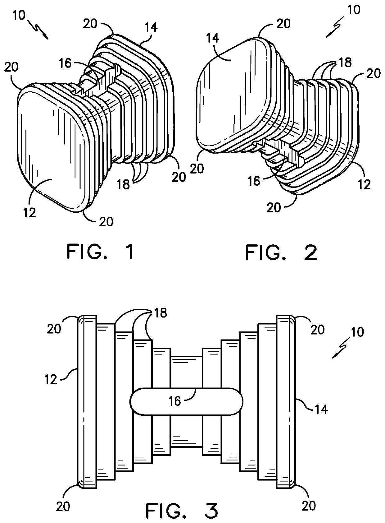
[0037]Referring now to FIGS. 1-3, a connector 10 according to one embodiment of the invention is shown. At least one connector 10 is used to join two adjacent mitered frame members. When two frame members of the frame are joined at a miter joint, slots formed in the abutting edges form a shape generally corresponding to the shape of the connector 10 into which the connector 10 is inserted for connecting together the two frame members.

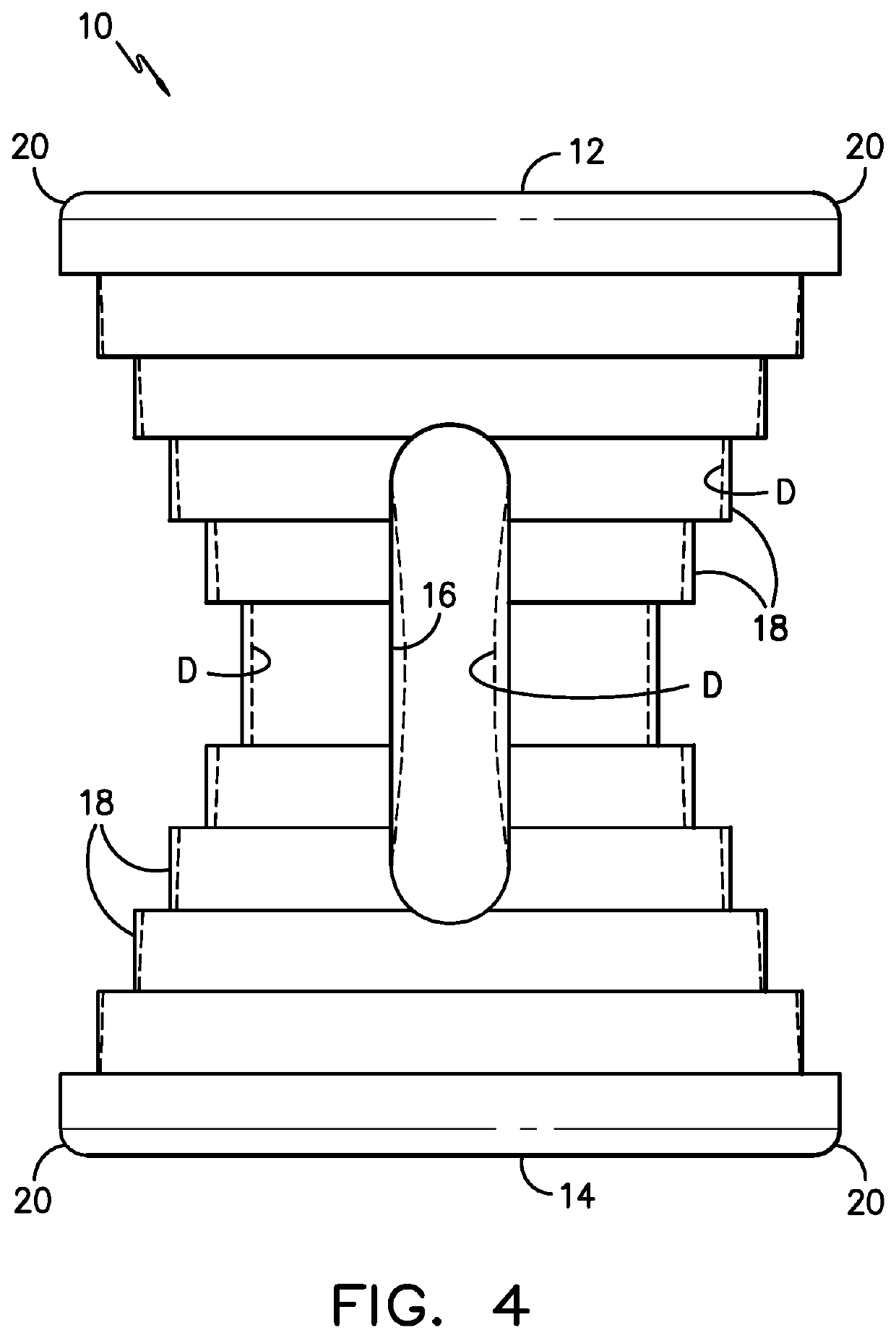
[0038]The connector 10 may be made of plastic, metal, wood, or any other suitable material. The connector 10 according to a preferred embodiment has an “hourglass”, “I” or “bowtie” shape with two relatively flat ends 12, 14 and a central void 16 that preferably extends through the connector 10 from one side to the other side. The connector 10 is symmetrical end to end and side to side with an inward taper from both ends 12, 14. This symmetry increases the versatility of the connector 10 and reduces user error by increasing the possible orientations whic...


PUM


Abstract

A connector is adapted for securing into a fixed position two frame members that are positioned to define a common miter joint and aligned slots to collectively define a single correspondingly-shaped connector opening. The connector includes a peripheral configuration corresponding to a peripheral configuration of the correspondingly-shaped opening. The connector may have a peripheral surface having on predetermined portions thereof a plurality of stepwise ridges adapted to contact with reduced friction only spaced-apart areas of sidewalls of the correspondingly-shaped opening. The connector may have at least one void in the connector to permit deformation sufficient to accommodate variations between the shape of the connector and the shape of the correspondingly-shaped opening. A method of using the connector is also disclosed.

Description

CROSS-REFERENCE TO RELATED APPLICATION[0001]This application claims the priority of U.S. Design Patent Application Nos. 29 / 708,006, 29 / 708,011, 29 / 708,012, and 29 / 708,014, all entitled “Dovetail Element for Mirror Frame Attachment,” all filed on Oct. 2, 2019, and all of which are hereby incorporated by reference in the entirety.TECHNICAL FIELD AND BACKGROUND OF THE INVENTION[0002]The invention relates generally to the field of frames and, more particularly to the assembly of picture and mirror frames using miter joint connectors to join adjacent, mitered frame members.[0003]There exists a wide variety of frame joinder methods. One such prior art frame assembly method includes inserting connectors of various shapes into slots or pockets formed in the edges of mitered butt joints by routing, for example. These connectors have varying shapes, such as an “hourglass,”“bowtie,” or “I”-shape, all defined by a peripheral shape that corresponds generally to the shape of the slots into which ...

Claims


Application Information

Patent Timeline
Patent Type & Authority Applications(United States)
IPC IPC(8): E06B3/968E06B3/972
CPCE06B3/9682E06B3/9725E06B3/9845A47G1/101
Inventor HUNTTING, LISAVAN DEURSEN, GARY
Owner BUTTON OPERATING CO LLC
Why Eureka
Try Eureka