Al technical title is built by PatSnap Al team. It summarizes the technical point description of the patent document.
a technology of light shields and trackers, applied in the field of optical navigation systems, can solve problems such as limited the number of navigational stars that may be used, required precision, and substantial problems
Pending Publication Date: 2021-04-15
CHARLES STARK DRAPER LABORATORY
View PDF5 Cites 7 Cited by
Summary
Abstract
Description
Claims
Application Information
AI Technical Summary
This helps you quickly interpret patents by identifying the three key elements:
Problems solved by technology
Method used
Benefits of technology
[0064]The camera may be automatically caused to capture an image. A portion, less than all, of the image may be automatically analyzed. The portion of the image that is analyzed corresponds to the portion of the camera field of view exposed to the scene.
[0065]The camera may include a plurality of image sensor arrays. Each image sensor array of the plurality of image sensor arrays may include a plurality of pixels. The method may further include reading a subset, less than all, of the pixels of the plurality of image sensor arrays. The subset may correspond to the selectable portion of the camera field of view exposed to the scene.
[0066]Yet another embodiment of the present invention provides a computer program product for exposing a selectable portion, l...
Problems solved by technology
However, the fixed view angle of a strapped-down star tracker limits the number of navigational stars that may be used.
However, aiming a prior art star tracker, relative to its vehicle, with the required precision poses substantial problems.
Stray light from the sun or another bright object poses problems for star cameras.
However, fixed sun shields are necessarily large, so they can b...
Method used
Image
Click on the blue label to locate the original text in one second.
Reading with bidirectional positioning of images and text.
Examples
Embodiment Construction
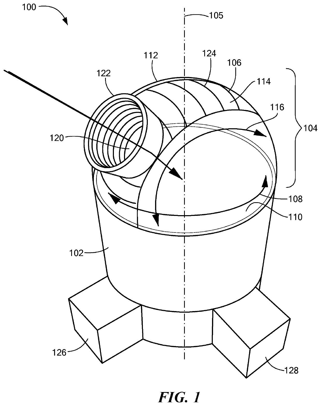
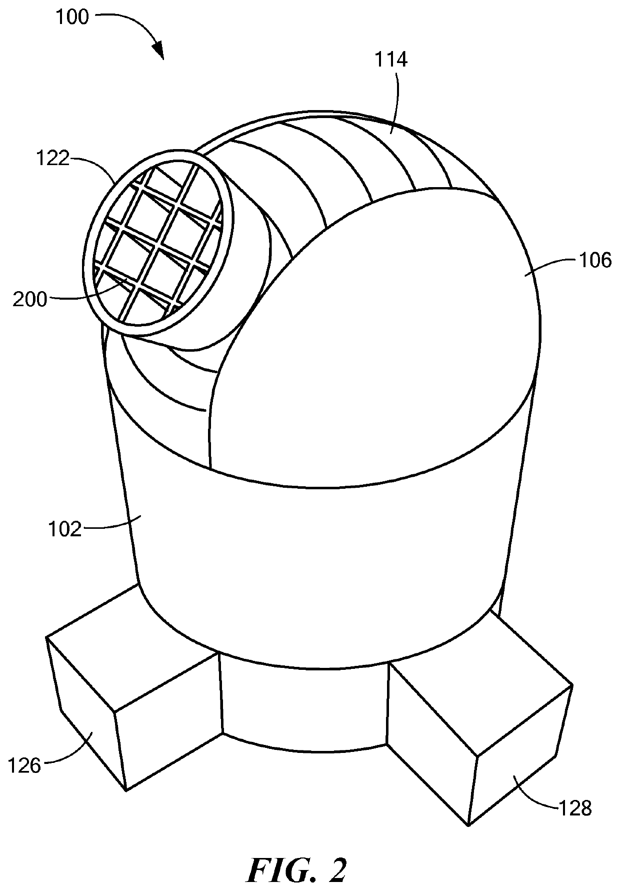
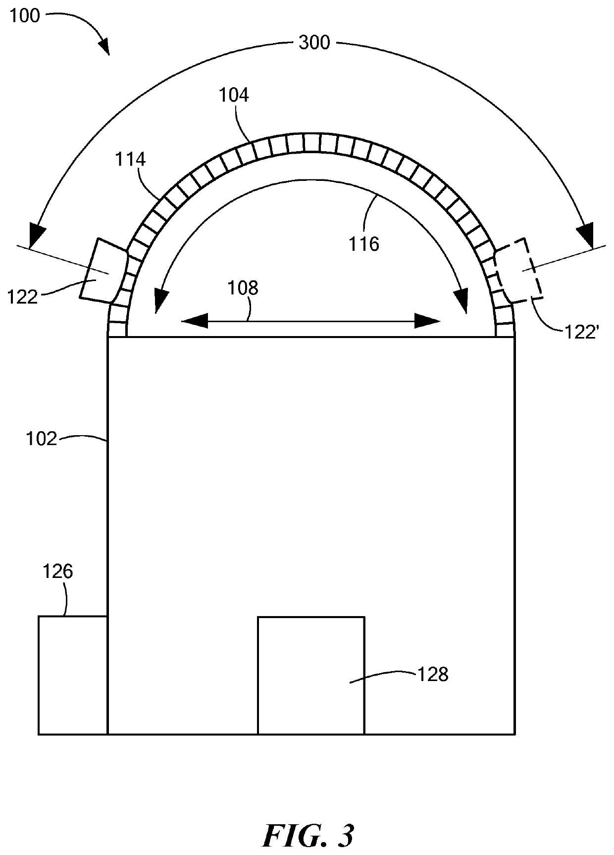
[0008]Embodiments of the present invention provides a star camera. The star camera includes a lens having a focal length and a field of view. The star camera also includes a pixelated digital image sensor oriented toward the lens and disposed a distance from the lens equal to the focal length of the lens, such that the lens projects an image of the field of view onto the sensor, thereby defining a light path from the field of view to the sensor. The star camera further includes a light blocker disposed within the light path. The star camera also includes a mechanical positioner coupled to the light blocker and configured to position the light blocker at an electronically selectable location within the light path, such that the light blocker blocks visibility by the sensor of a selectable portion of the field of view. The light blocker has a size such that the portion of the field of view blocked by the light blocker has an angular diameter of at least 30′ and at most 45′.
[0009]In so...
PUM
Abstract
A navigation system includes a star camera having a field of view. The star camera includes a sun shields that selectively block portions of the star camera's field of view, to prevent unwanted light, such as light from the sun or moon, reaching image sensors of the star cameras. Some sun shields include x-y stages or r-θ stages to selectively position a light blocker to block the unwanted light. Some sun shields use positionable partially overlapping orthogonally polarized filters to block the unwanted light. Some sun shields use counter-wound spiral windows that are selectively rotated to block the unwanted light. Some sun shields a curved surface that defines a plurality of apertures fitted with individual mechanical or electronic shutters.
Description
CROSS REFERENCE TO RELATED APPLICATIONS[0001]This application is a continuation-in-part of U.S. patent application Ser. No. 15 / 459,557, filed Mar. 15, 2017, titled “Navigation System with Monocentric Lens and Curved Focal Plane Sensor,” which is a divisional of U.S. patent application Ser. No. 14 / 548,021, filed Nov. 19, 2014, titled “Navigation System with Monocentric Lens and Curved Focal Plane Sensor,” which is a continuation-in-part of U.S. patent application Ser. No. 13 / 893,987, filed May 14, 2013, now U.S. Pat. No. 9,544,488, issued Jan. 10, 2017, titled “Star Tracker with Steerable Field-of-View Baffle Coupled to Wide Field-of-View Camera,” the entire contents of each of which are hereby incorporated by reference herein, for all purposes.TECHNICAL FIELD[0002]The present invention relates to optical navigation systems and, more particularly, to adjustable light shields for optical navigation systems, such as star trackers.BACKGROUND ART[0003]Most artificial satellites, spacecra...
Claims
Application Information
Patent Timeline
Application Date:The date an application was filed.
Publication Date:The date a patent or application was officially published.
First Publication Date:The earliest publication date of a patent with the same application number.
Issue Date:Publication date of the patent grant document.
PCT Entry Date:The Entry date of PCT National Phase.
Estimated Expiry Date:The statutory expiry date of a patent right according to the Patent Law, and it is the longest term of protection that the patent right can achieve without the termination of the patent right due to other reasons(Term extension factor has been taken into account ).
Invalid Date:Actual expiry date is based on effective date or publication date of legal transaction data of invalid patent.