Dating system for molds

a mold and date technology, applied in the field of mold date system, can solve the problems of mold damage, loss of function, and inability to use screwdrivers,

Pending Publication Date: 2021-05-06
COMML DE UTILES Y MOLDES
View PDF1 Cites 0 Cited by
  • Summary
  • Abstract
  • Description
  • Claims
  • Application Information

AI Technical Summary

Benefits of technology

[0021]Therefore, an objective of the present invention is to provide a dating system for molds that allows the information to be read much more clearly on the part.
[0024]The dating system according to the present invention is a new traceability element that allows the marking of the date of manufacture with extreme precision, with minimal dimensions and with an unprecedented reading quality in the marking of the date on the plastic parts, an issue of vital importance for production control.
[0035]Advantageously, the locking element, the handling tool and / or the storage element comprises one or more magnets duly polarized to prevent accidental loss of the interchangeable inserts and to fix them in their proper position.
[0037]With the dating system for molds according to the present invention, at least the following advantages are achieved, among others:
[0041]In addition, it allows the part not to present any protrusion, ensuring a completely sharp and functional appearance, which is especially important in parts whose walls are very thin, for example, in the cosmetic or pharmaceutical industry.

Problems solved by technology

As the arrows are deep enough for the screwdriver, the markers are not suitable for thin plastic parts, as well as picking up dirt in the arrow area over time.
There are markers with the numbers in high relief, but to be able to manipulate them, the arrow is also in low relief, so they lose their functionality.
In all cases, the use of a screwdriver is unavoidable to rotate the central shaft so that the arrow indicates the corresponding number.
In these cases, sometimes due to lack of skill of the operator, poor visibility due to the position of the marker or misuse of the screwdriver, damage occurs to the mold, or the position of the arrow(s) is incorrectly marked and the parts are marked with wrong data.
Consequently, changing the marker data becomes an uncomfortable task and it is foreseeable that the part will not be controlled as required by the product requirements and it is practically impossible for all the parts to reflect the veracity of the data that is stipulated as a guarantee of manufacturing control.
Another drawback of conventional mold markers is that the information they provide is limited and it can be confusing at times.
This is because the information varies depending on the orientation of the arrow, and this arrow can be difficult to see.
Furthermore, the information that can be provided is limited, usually month and year, occupying a considerable space in the piece, since all the months of the year are included, and the arrow is oriented towards one of them.

Method used


Image

  • Dating system for molds
  • Dating system for molds
  • Dating system for molds

Examples


Embodiment Construction

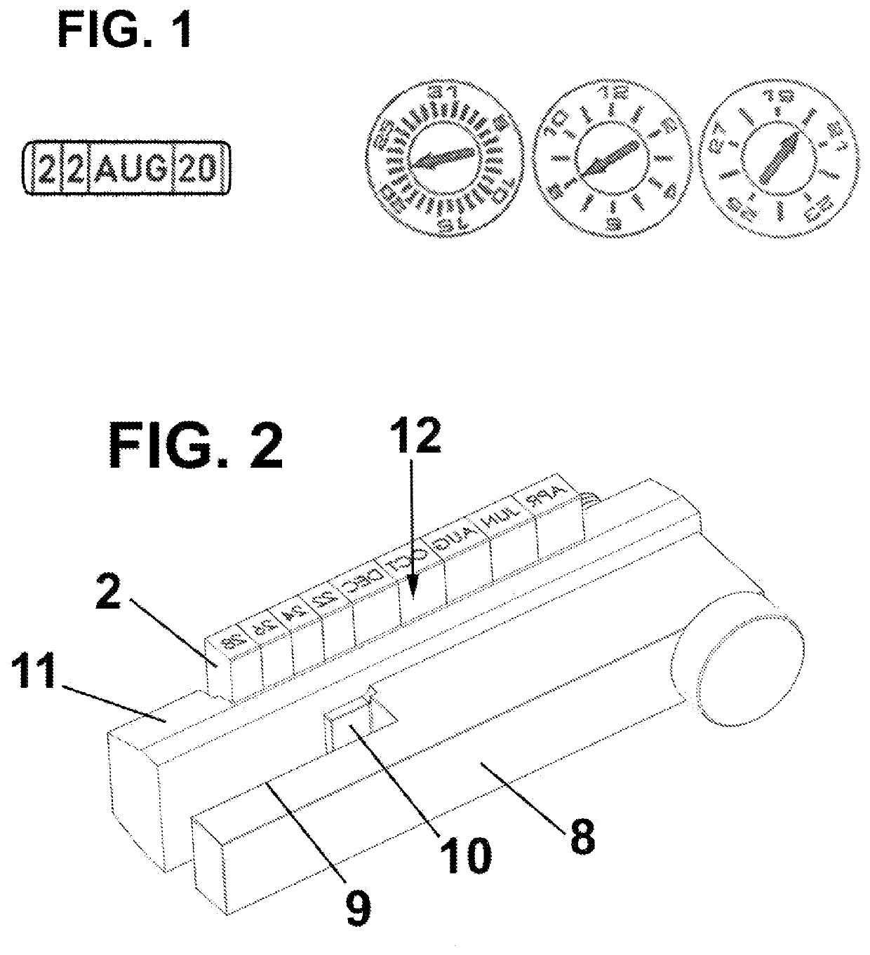
[0048]As indicated above and as shown in FIG. 1, the dating system of the present invention completely changes the geometry of the mold dating systems, and instead of being circular with an arrow pointing only to one of the information of the circle (on the right in FIG. 1), the dating system of the present invention only includes the information of the date, for example, the month and year (on the left in FIG. 1), preferably in a linear arrangement, that is, indicating the date with letters and / or numbers forming a line.

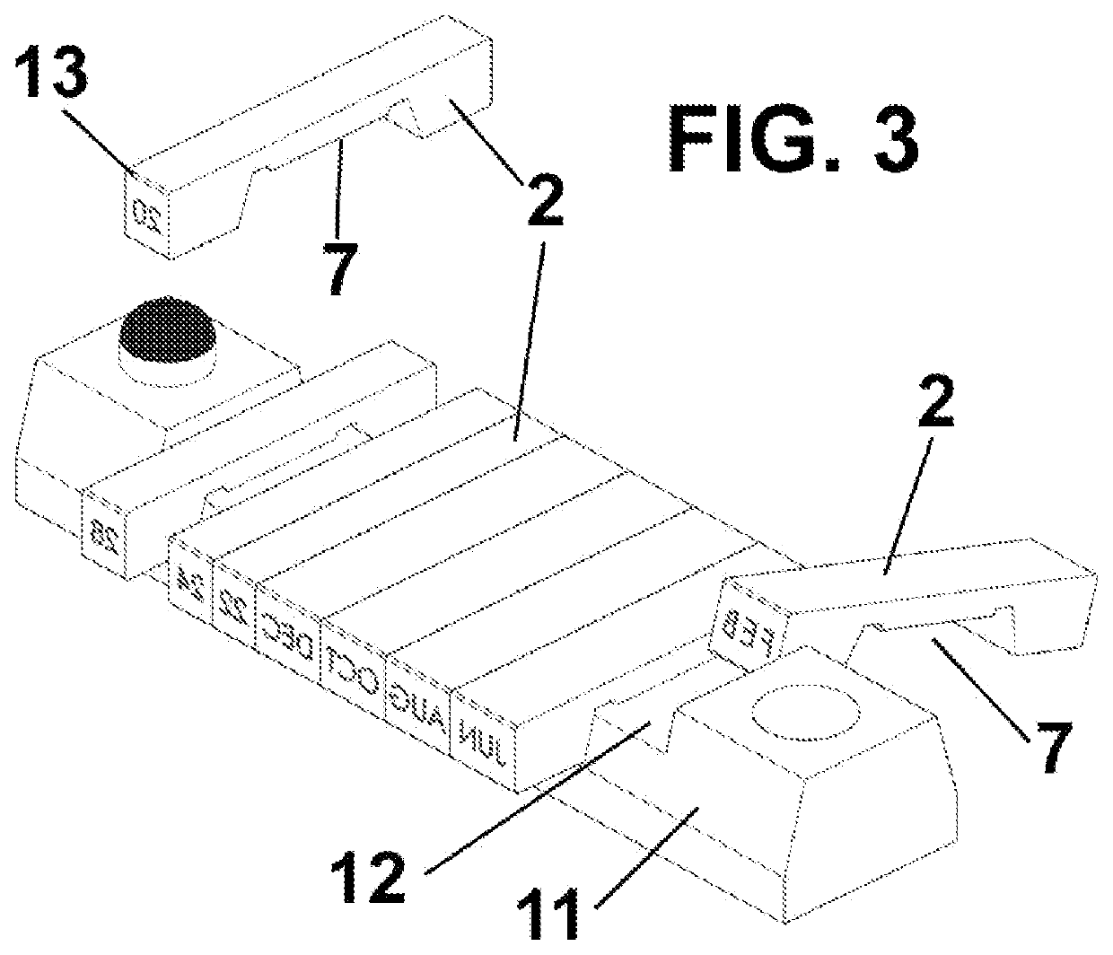
[0049]For this, the dating system for molds according to the present invention comprises a marking element 1 that engraves a date on a part that is molded in the mold.

[0050]Said date indicates the date of manufacture of the part that is molded made up of letters and / or numbers, which can include the month and the year, or the day, the month and the year, or the number of the week and the year, or any combination of such information to provide the date.

[0051]Preferab...


PUM

PropertyMeasurementUnit
storage areaaaaaaaaaaa
perimeteraaaaaaaaaa
diameteraaaaaaaaaa

Abstract

The dating system for molds comprises a marking element (1) that engraves a determined date; wherein said marking element (1) comprises interchangeable inserts (2) indicating said determined date, said determined date being defined by letters and / or numbers, forming a line. It permits to obtain the advantages of: the reading of the information is much clearer than the traditional date stamps; it requires a minimum space, which allows to adapt it to practically any mold; and it is much more dynamic than traditional daters, as it can provide date information in multiple formats, such as day and month, or week and year number, or combinations thereof.

Description

[0001]The present invention relates to a dating system for molds.BACKGROUND OF THE INVENTION[0002]In the manufacture of plastic parts by injection, it is common to mark the manufacturing date on the injected part to know at all times the real traceability of the production process and to know the complete history, both of the material used and the guarantee of its origin.[0003]For this purpose, it is usual that the date is marked in relief at the moment of injection.[0004]For this, there are different models of markers, which are engraved with different numbers arranged on a cylinder that has the numbers engraved on the circular perimeter depending on whether you want to engrave the day, week, month, year, etc.[0005]For example, in the month and year model, the numbers from 1 to 12 are engraved on the perimeter, as a clock, and inside this same cylinder, and so that it can rotate on its own axis, it carries another smaller diameter cylinder that includes an arrow to indicate the num...

Claims


Application Information

Patent Timeline
Patent Type & Authority Applications(United States)
IPC IPC(8): B29C45/37
CPCB29C45/374B29C33/428B29C45/372
Inventor NAVARRA PRUNA, ALBERTO
Owner COMML DE UTILES Y MOLDES
Why Eureka
Try Eureka