Telescopic fan cage and apparatus case therewith

a fan cage and fan technology, applied in the field of apparatus cases, can solve the problems of limiting the structure design the edge of the side wall is not suitable for forming an inwardly-bent structure, and the space utilization of the apparatus case, so as to increase the flexibility of the industry design

Active Publication Date: 2021-05-06
WISTRON CORP
View PDF0 Cites 8 Cited by
  • Summary
  • Abstract
  • Description
  • Claims
  • Application Information

AI Technical Summary

Benefits of technology

[0003]An objective of the invention is to provide a telescopic fan cage, which uses its telescopic property in structure to easily avoid structural interference with other structures during an installation.
[0004]A telescopic fan cage according to the invention includes a main frame and a side frame. The side frame and the main frame are slidably connected with each other to form a fan installation space. The side frame is operable to slide toward the main frame to shrink the fan installation space; the side frame is also operable to slide away relative to the main frame to expand the fan installation space. Thereby, the telescopic fan cage increases the flexibility of installation and movement by use of its telescopic property in structure.
[0005]Another objective of the invention is to provide an apparatus case, which includes the above telescopic fan cage and uses its telescopic property in structure to easily avoid structural interference with other structures of the apparatus case during an installation of the telescopic fan cage.
[0007]Compared with the prior art, in the telescopic fan cage and the apparatus case therewith according to the invention, the telescopic fan cage has the telescopic property in structure, so during the process of installing the telescopic fan cage into the casing or taking the telescopic fan cage out of the casing, it is practicable to implement the process by a single hand without structural interference between the telescopic fan cage and other structures of the apparatus case, which can increase the flexibility of industry design of the apparatus case and the usage of the interior space of the apparatus case.

Problems solved by technology

For example, the edge of the side wall is not suitable to form an inwardly-bent structure (e.g. fillet, which will limit the width of the passage).
Even if some space of the passage is not occupied by the cage (e.g. the space above the fixed cage), it is unable to fix a structure therein, which will influences the space usage of the apparatus case.
The casing needs to reserve space for convenience of the above manipulation, which limits the structure design of the casing and also influences the industry design of the apparatus case.

Method used


Image

  • Telescopic fan cage and apparatus case therewith
  • Telescopic fan cage and apparatus case therewith
  • Telescopic fan cage and apparatus case therewith

Examples


Embodiment Construction

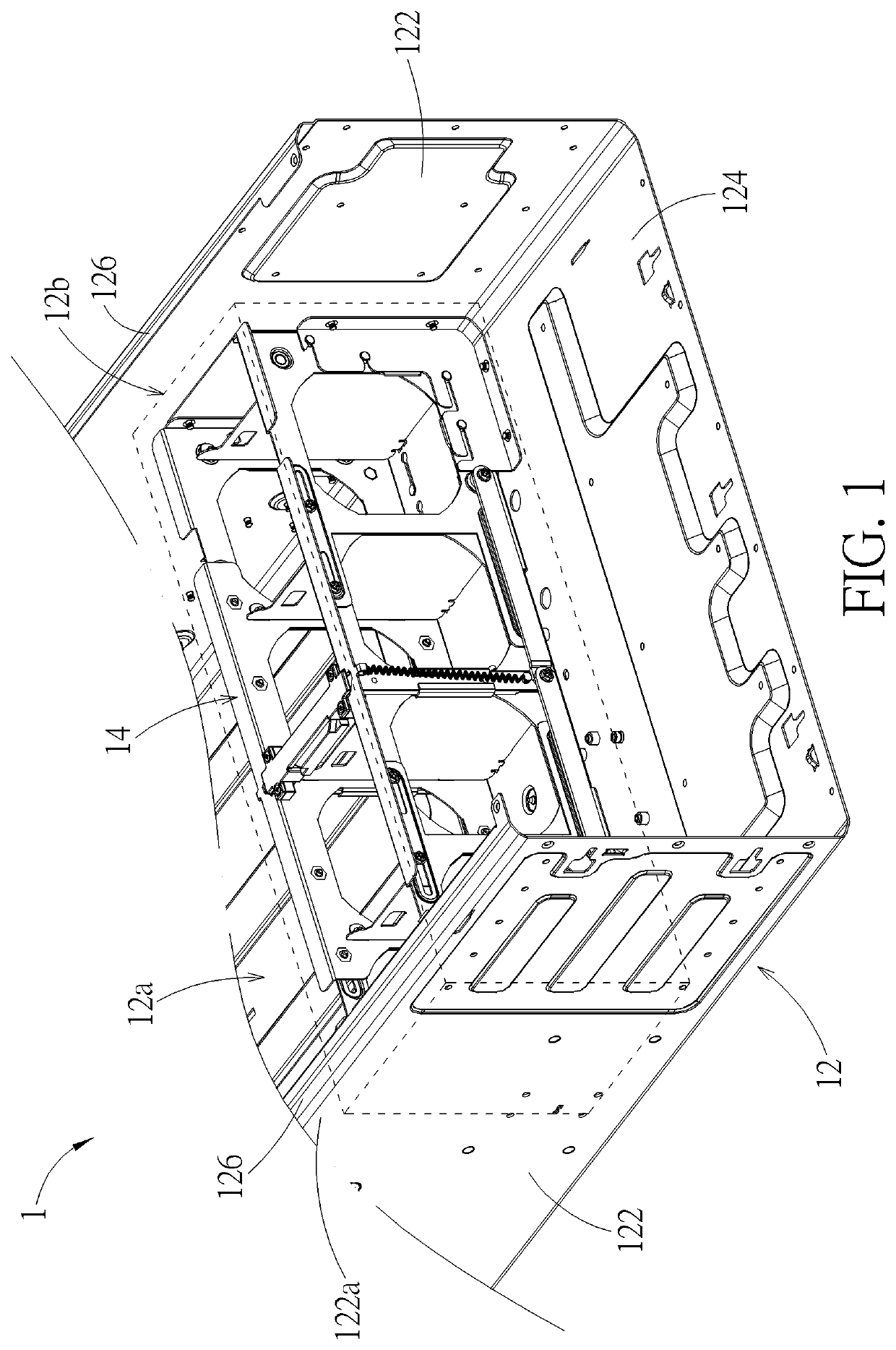
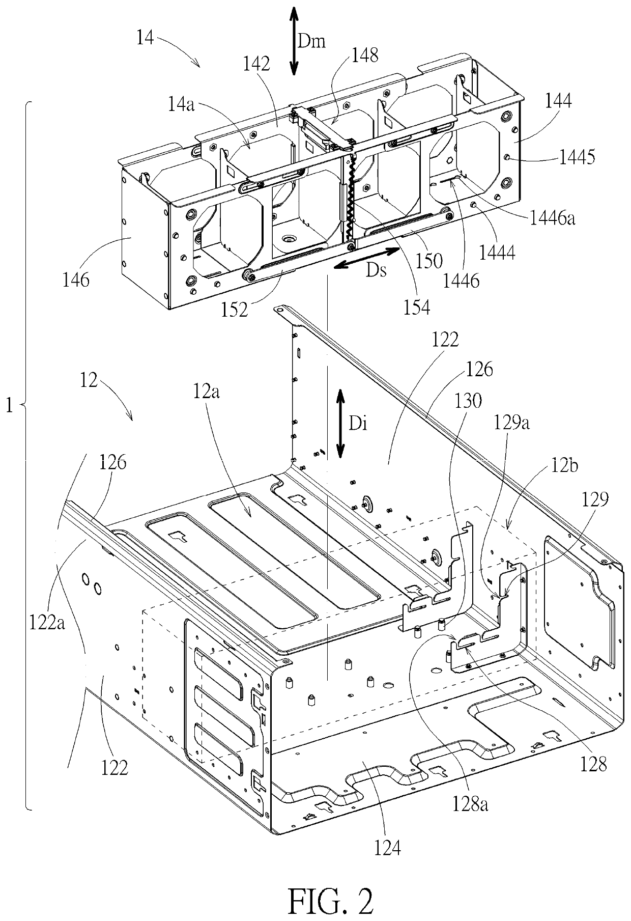
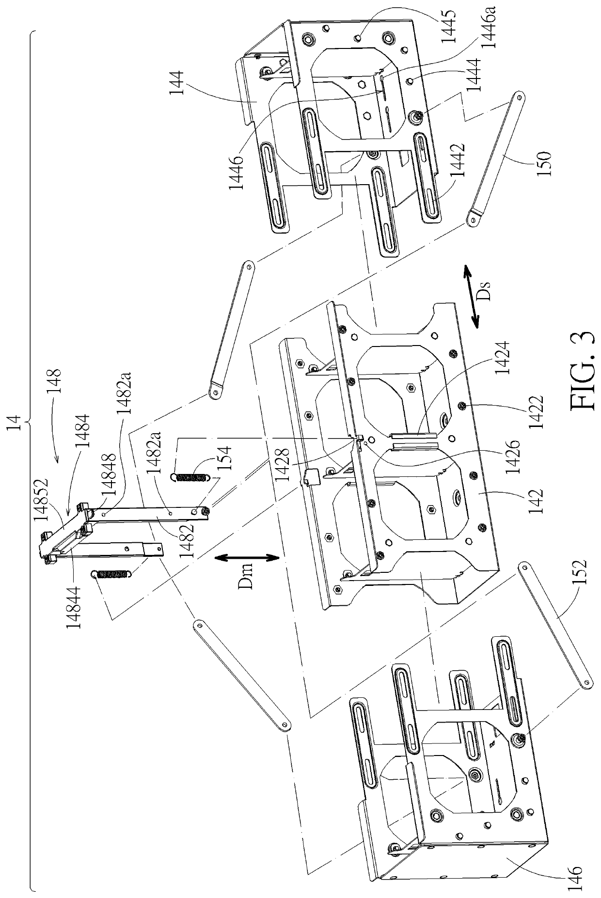
[0020]Please refer to FIG. 1 and FIG. 2. An apparatus case 1 according to an embodiment includes a casing 12 and a telescopic fan cage 14. The telescopic fan cage 14 is detachably disposed in the casing 12. The telescopic fan cage 14 includes a main frame 142, a first side frame 144, and a second side frame 146. The first side frame 144 and the second side frame 146 are respectively slidably connected to the main frame 142, so that the telescopic fan cage 14 as a whole has a telescopic property in structure. Therein, the main frame 142, the first side frame 144, and the second side frame 146 together form a fan installation space 14a. The first side frame 144 and the second side frame 146 can slide toward the main frame 142 to shrink the fan installation space 14a and also can slide away relative to the main frame 142 to expand the fan installation space 14a. Therefore, during the process of installing the telescopic fan cage 14 into the casing 12 or moving the telescopic fan cage 1...


PUM


Abstract

A telescopic fan cage includes a main frame and a side frame which are slidably connected with each other to form a fan installation space. The side frame is capable of sliding toward the main frame to shrink the fan installation space, or sliding away relative to the main frame to expand the fan installation space. An apparatus case includes a casing and the telescopic fan cage. The telescopic fan cage is detachably disposed in the casing. Therein, the side frame is capable of sliding toward the main frame to shrink the fan installation space, so that the telescopic fan cage is at a transit state for moving in or out the casing; the side frame is capable of sliding away relative to the main frame to expand the fan installation space, so that the telescopic fan cage is at an installation state for being fixed in the casing.

Description

BACKGROUND OF THE INVENTION1. Field of the Invention[0001]The present invention relates to an apparatus case having a fan cage, and more particularly to a telescopic fan cage and an apparatus case therewith.2. Description of the Prior Art[0002]Conventional apparatus cases (e.g. for servers) are usually equipped with fans. A cage used for fixing and supporting fans is usually designed to be separable from the casing of the apparatus case, which is conducive to modularization. In principle, the casing needs to provide a passage sufficient for the cage to pass through, so that the cage will not structurally interfere with the casing during an installation of the cage. In general, the cage is fixed to two opposite side walls of the casing, so the structure design of the side wall is limited and the industry design of the apparatus case is also influenced indirectly. For example, the edge of the side wall is not suitable to form an inwardly-bent structure (e.g. fillet, which will limit t...

Claims


Application Information

Patent Timeline
Patent Type & Authority Applications(United States)
IPC IPC(8): F04D29/64F04D19/00H05K7/14H01L23/40
CPCF04D29/646H01L23/40H05K7/14F04D19/002G06F1/183G06F1/20F04D29/522F05D2250/41F04D29/601F04D25/166H05K7/20172H05K7/1415H05K5/0208H05K5/0221
Inventor YANG, JIAN BANGFU, ZHAOPING
Owner WISTRON CORP
Why Eureka
Try Eureka