Optically Excited Biopotential Phantom

a biopotential phantom, optically excited technology, applied in the field of optically excited biopotential phantom, can solve the problems of preventing accurate signal evaluation and adversely affecting signal quality

Pending Publication Date: 2021-05-13
NEXTSENSE INC
View PDF7 Cites 4 Cited by
  • Summary
  • Abstract
  • Description
  • Claims
  • Application Information

AI Technical Summary

Benefits of technology

[0003]The technology relates to a system for simulating bio signals such as brain bio-signals, as well as detection and evaluation of such signals. This system can be used for medical or non-medical purposes, e.g., to simulate or evaluate certain medical conditions, to provide a brain control interface (BCI) for a computer application, etc. As discussed further herein, a physical brain-type phantom is employed that is configured to simulate various biopotentials in a repeatable and calibrated manner. Furthermore, the phantom structure does not need to be homogenous. Rather, it may have different layers or regions to mimic the skull, brain, skin, hair, etc.

Problems solved by technology

However, the placement and amount of wiring may create interference (e.g., crosstalk) that can adversely impact signal quality and prevent accurate signal evaluation.

Method used


Image

  • Optically Excited Biopotential Phantom
  • Optically Excited Biopotential Phantom
  • Optically Excited Biopotential Phantom

Examples


example implementation

and Operation

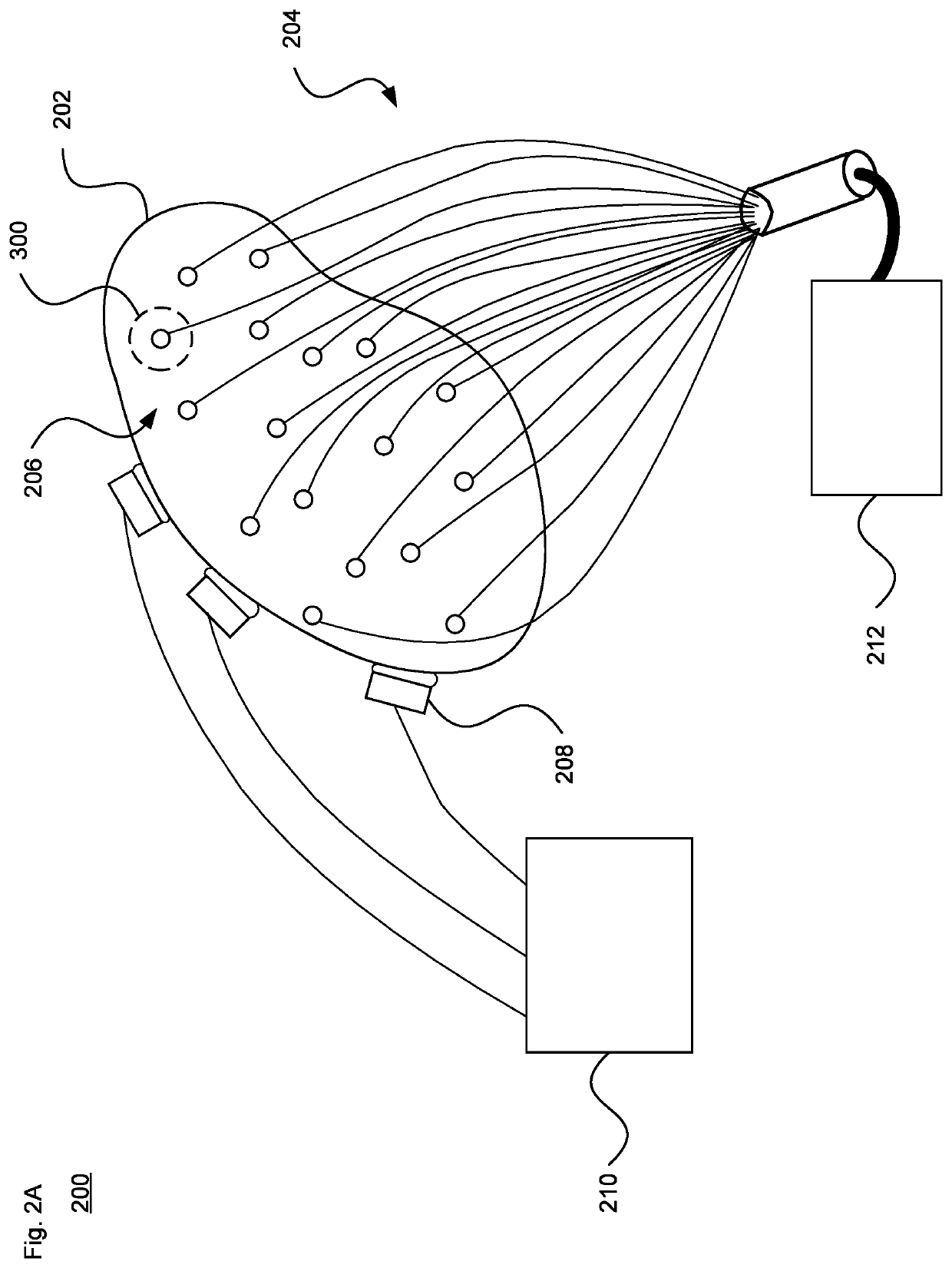
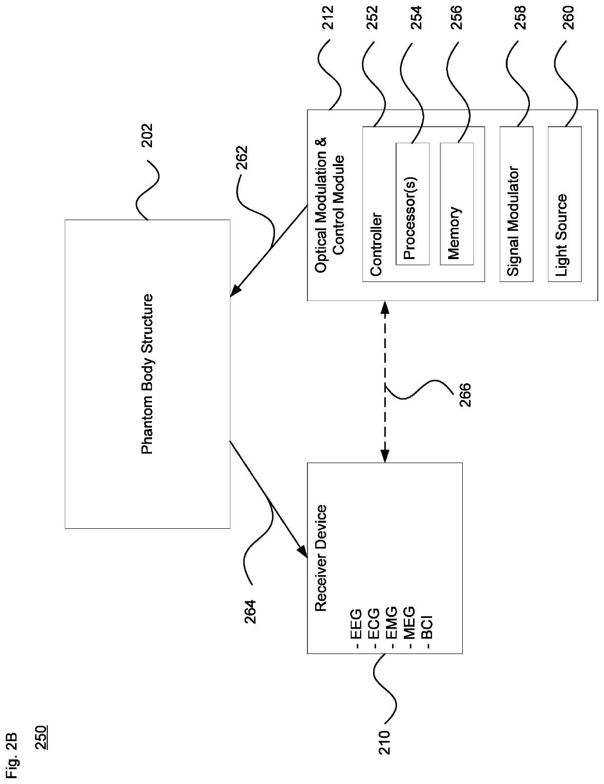
[0030]According to one aspect of the technology, the set of optical fibers 204 is at least partly arranged within the phantom body structure 202. A first end of each optical fiber is coupled to the optical modulation and control module 212, while an opposing second end is disposed within the phantom body structure 202 remote from the module 212. Each fiber is configured to convey a modulated light signal to a particular location along or otherwise within the phantom body structure. The modulation can be accomplished in various ways by the optical modulation and control module. This can include varying the intensity, pulse width, pulse duration, polarization and / or color, etc. of the propagated light.

[0031]The second end of each fiber is coupled to an optode. Each optode may be, e.g., a photodiode or light-emitting diode (LED) such as a surface mount LED. FIG. 3 illustrates an enlarged view of dashed region 300 of FIG. 2A. As shown in this view by dashed line 302, a modu...


PUM


Abstract

The technology provides a system and method for simulating and detecting bio signals such as brain bio-signals. The technology can be used for medical or non-medical purposes, for instance to simulate or evaluate certain medical conditions using a physical brain-type phantom body. A set of optical fibers provides modulated signals received from an optical signal modulator, which is managed by a controller to generate repeatable signals with high fidelity. The modulated signals are received by a set of emission elements such as photoreceivers or other optical electrodes disposed within or otherwise about the phantom body. The emission elements output electrical signals corresponding to the input modulated optical signals. The electrical signals are detected by a set of sensors. The sensors are coupled to a receiver device that is able to evaluate the electrical signals, such as for an electroencephalograph (EEG), electrocardiogram (ECG), electromyogram (EMG) or magnetoencephalography (MEG) diagnostic system.

Description

CROSS-REFERENCE TO RELATED APPLICATION[0001]The present application is related to U.S. application Ser. No. 16 / 682,621, entitled Opto-Electronic Biopotential Controller, Attorney Docket No. ATOZX 3.0F-2053 [9019], filed concurrently herewith, the entire disclosure of which is incorporated by reference herein.BACKGROUND[0002]Physical bio-phantoms have been used to simulate various types of human tissue, including the brain. In this type of system, a set of electrodes may be placed at various points along the phantom by running wires through it. The electrodes are actuated with electrical pulses. However, the placement and amount of wiring may create interference (e.g., crosstalk) that can adversely impact signal quality and prevent accurate signal evaluation. For instance, magnetoencephalography (MEG) may be significantly affected by electrical crosstalk.BRIEF SUMMARY[0003]The technology relates to a system for simulating bio signals such as brain bio-signals, as well as detection an...

Claims


Application Information

Patent Timeline
Patent Type & Authority Applications(United States)
IPC IPC(8): A61B5/0402A61B5/04A61B5/0476A61B5/0488
CPCA61B5/04021A61B5/04008A61B2017/00707A61B5/0488A61B5/0476A61B2560/0233A61B5/1495A61B5/245A61B5/30A61B5/291A61B2090/0807A61B5/319A61B5/369A61B5/389A61B2560/0223
Inventor MIROV, RUSSELL
Owner NEXTSENSE INC
Why Eureka
Try Eureka