
Failure detection device, failure detection method, and failure detection program

a failure detection and failure detection technology, applied in the field of failure detection devices, failure detection methods, failure detection programs, etc., can solve problems such as the inability to use the driving support function and the failure to operate the driving support function

Active Publication Date: 2021-05-13
MITSUBISHI ELECTRIC CORP
View PDF0 Cites 0 Cited by
  • Summary
  • Abstract
  • Description
  • Claims
  • Application Information

AI Technical Summary

Benefits of technology

The invention can detect if a sensor has failed by analyzing if there is any difference in data collected from an abnormal object compared to data collected from a normal object. This way, the sensor can be tested without needing a pre-made model.

Problems solved by technology

When the sensor for realizing the driving support function fails completely, the driving support function cannot be used.
However, when an anomaly occurs only in a part of the sensing range of the sensor, as in a case where dirt or dust adheres to the sensor, a possibility exists that a detection result indicating there is no obstacle may be obtained, although there is actually an obstacle.
When such a detection result is obtained, a possibility exists that the driving support function may malfunction.

Method used


Image

  • Failure detection device, failure detection method, and failure detection program
  • Failure detection device, failure detection method, and failure detection program
  • Failure detection device, failure detection method, and failure detection program

Examples


first embodiment

[0025]***Description of Configuration***

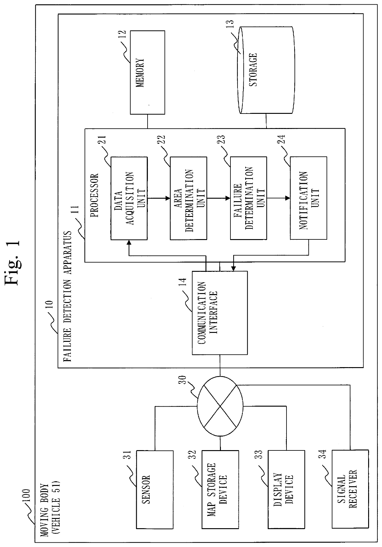
[0026]A configuration of a failure detection apparatus 10 according to a first embodiment will be described with reference to FIG. 1.

[0027]FIG. 1 illustrates a state in which the failure detection apparatus 10 is mounted on a moving body 100. The moving body 100 is a vehicle, a ship, or the like. In the first embodiment, the moving body 100 will be described as a vehicle 51.

[0028]Note that the failure detection apparatus 10 may be implemented in a form integrated with or in a form inseparable from the moving body 100 or another functional component that is illustrated. Alternatively, the failure detection apparatus 10 may be implemented in a detachable form or in a separable form.

[0029]The failure detection apparatus 10 is a computer.

[0030]The failure detection apparatus 10 has hardware of a processor 11, a memory 12, a storage 13, and a communication interface 14. The processor 11 is connected with other hardware components via signal lines a...


PUM


Abstract

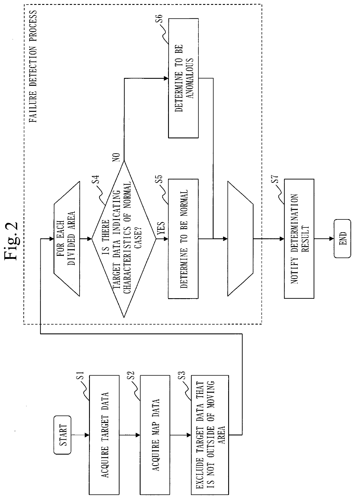
A failure detection apparatus (10) acquires, as target data, sensor data output in a past reference period by a sensor (31), such as a millimeter wave radar or LiDAR (Light Detection And Ranging), mounted on a moving body (100). The failure detection apparatus (10) determines whether detected data indicating a characteristic of a detected object indicated by normal data, which is sensor data output when the sensor (31) is normal, is included in the acquired detected data in the past reference period. In this way, the failure detection apparatus (10) determines whether a failure has occurred in the sensor (31).

Description

TECHNICAL FIELD[0001]The present invention relates to a technology for detecting a failure in a sensor mounted on a moving body.BACKGROUND ART[0002]The rise in safety awareness and the pursuit of convenience have led to an increase in automobiles equipped with a driving support function such as an emergency automatic braking function. In order to realize the driving support function, there may be a case where a sensor that emits radio waves or light, such as a millimeter wave radar or LiDAR (Light Detection And Ranging), is employed.[0003]When the sensor for realizing the driving support function fails completely, the driving support function cannot be used. However, when an anomaly occurs only in a part of the sensing range of the sensor, as in a case where dirt or dust adheres to the sensor, a possibility exists that a detection result indicating there is no obstacle may be obtained, although there is actually an obstacle. When such a detection result is obtained, a possibility ex...

Claims


Application Information

Patent Timeline
Patent Type & Authority Applications(United States)
IPC IPC(8): G01S7/40G01S13/931G01S17/931G01S13/86G01S17/86G07C5/08
CPCG01S7/40G01S13/931G01S17/931G01S2013/9323G01S17/86G07C5/0808G07C5/0816G01S13/867G01S7/497G01S2007/4975G01S7/4039
Inventor TSUSHIMA, NAOYUKITANIMOTO, MASAHIKOABUKAWA, MASAHIRO
Owner MITSUBISHI ELECTRIC CORP
Learn More