
Fuel cell system

a fuel cell and system technology, applied in the field of fuel cell systems, to achieve the effect of reducing, and effectively eliminating or reducing situations

Active Publication Date: 2021-05-27
HONDA MOTOR CO LTD
View PDF0 Cites 2 Cited by
  • Summary
  • Abstract
  • Description
  • Claims
  • Application Information

AI Technical Summary

Benefits of technology

The present invention provides a fuel cell system that prevents water stored in a gas liquid separator from flowing into the gas inlet channel. The gas inlet section includes an inner protrusion that guides a dry gas and the bottom surface of the gas liquid separation chamber is inclined to further prevent water from flowing into the gas inlet channel. This results in the removal or reduction of situations where water flows from the gas liquid separator and enters the gas inlet channel, which improves the efficiency and reliability of the fuel cell system.

Problems solved by technology

As a result, there is a concern that the stored water in the gas liquid separator may flow into the gas inlet channel.

Method used


Image

  • Fuel cell system
  • Fuel cell system
  • Fuel cell system

Examples


Embodiment Construction

[0020]Hereinafter, preferred embodiments of a fuel cell system according to the present invention will be described with reference to the accompanying drawings.

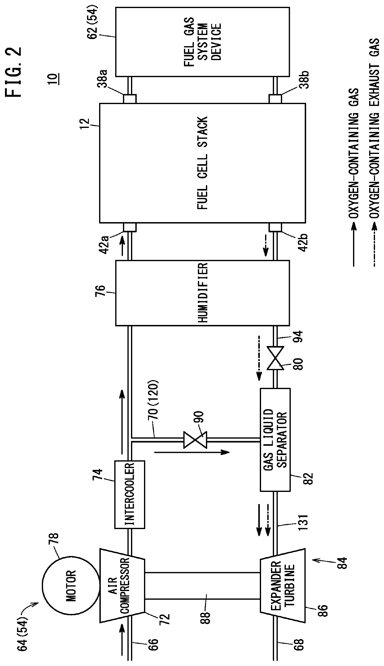
[0021]For example, a fuel cell system 10 according to an embodiment of the present invention is mounted in a fuel cell vehicle (fuel cell electric automobile).

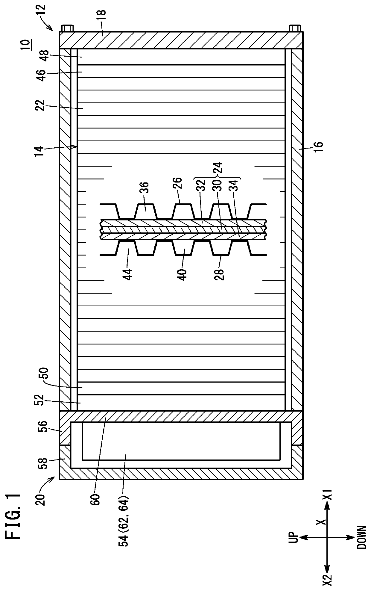
[0022]As shown in FIG. 1, the fuel cell system 10 includes a fuel cell stack 12. The fuel cell stack 12 includes a cell stack body 14, a stack case 16, an end plate 18, and an auxiliary device case 20. The cell stack body 14 is formed by stacking a plurality of power generation cells 22 in one direction (indicated by an arrow X, horizontal direction).

[0023]The power generation cell 22 includes a membrane electrode assembly (hereinafter referred to as the “MEA 24”), and a pair of separators 26, 28 sandwiching the MEA 24 from both sides. For example, the MEA 24 includes an electrolyte membrane 30, an anode 32 provided on one surface of the electrolyte membrane 30, and a c...


PUM

PropertyMeasurementUnit
poweraaaaaaaaaa
regenerate energyaaaaaaaaaa
electrochemical reactionsaaaaaaaaaa

Abstract

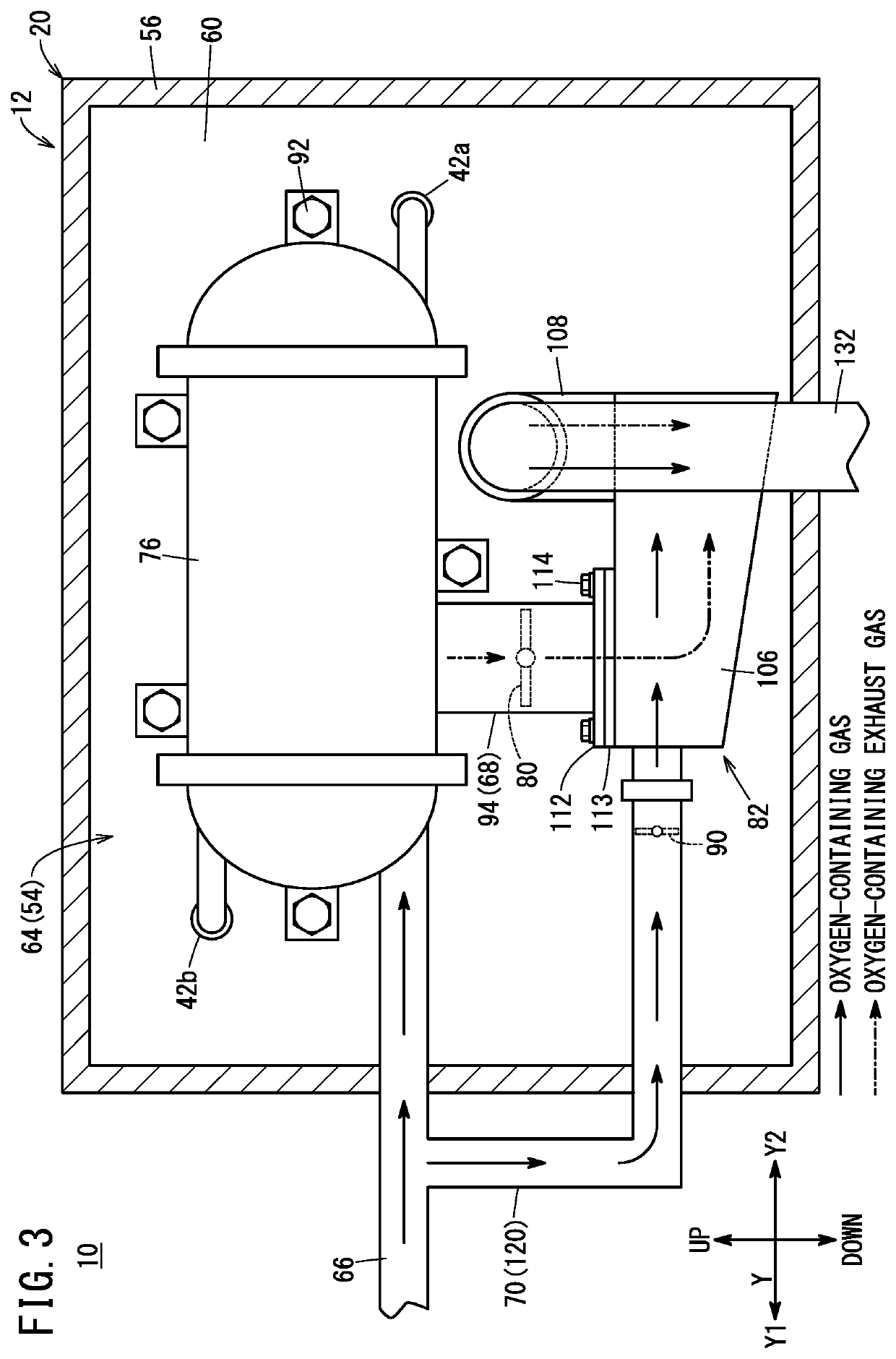
A gas liquid separator of a fuel cell system includes a first gas liquid separation chamber capable of storing water content separated from an oxygen-containing exhaust gas, a second gas liquid separation chamber positioned above the first gas liquid separation chamber, and connected to the first gas liquid separation chamber, an inlet, an outlet, and a gas inlet channel for guiding a dry gas into the first gas liquid separation chamber. A gas inlet section forming the gas inlet channel includes an inner protrusion protruding into an upper space of the first gas liquid separation chamber, and a bottom surface of the first gas liquid separation chamber is inclined downward in a direction in which the inner protrusion extends.

Description

CROSS-REFERENCE TO RELATED APPLICATION[0001]This application is based upon and claims the benefit of priority from Japanese Patent Application No. 2019-211062 filed on Nov. 22, 2019, the contents of which are incorporated herein by reference.BACKGROUND OF THE INVENTIONField of the Invention[0002]The present invention relates to a fuel cell system.Description of the Related Art[0003]The fuel cell system includes a fuel cell stack formed by stacking a plurality of power generation cells. Each of the power generation cells performs power generation by electrochemical reactions of a fuel gas and an oxygen-containing gas. An oxygen-containing exhaust gas containing water produced in power generation of the power generation cells (oxygen-containing off gas) flows through the discharge channel provided in the fuel cell stack.[0004]For example, Japanese Laid-Open Patent Publication No. 2007-184144 discloses structure where a gas liquid separator is provided in a discharge channel. The gas l...

Claims


Application Information

Patent Timeline
Patent Type & Authority Applications(United States)
IPC IPC(8): H01M8/04119H01M8/04082
CPCH01M8/04164H01M8/04126H01M8/04201H01M8/04089H01M8/2483Y02E60/50H01M8/04111H01M8/04014H01M2250/20H01M8/1004Y02T90/40
Inventor YOSHITOMI, RYOICHI
Owner HONDA MOTOR CO LTD
Learn More