
Split Microplate and Vials

a microplate and split technology, applied in the field of split microplates and vials, can solve the problem of not having a microplate that meets all the desired requirements, and achieve the effect of convenient handling

Active Publication Date: 2021-06-10
QIS INC
View PDF6 Cites 0 Cited by
  • Summary
  • Abstract
  • Description
  • Claims
  • Application Information

AI Technical Summary

Benefits of technology

The present invention provides a microplate and vial combination that allows for easier handling and robotic access. The microplate is split into two parts, and the vials are held in a raised position to prevent spilling. The vials remain vertical even when raised, ensuring consistent and accurate access.

Problems solved by technology

To Applicants' knowledge, there is no microplate available that satisfies all of the desired requirements.

Method used


Image

  • Split Microplate and Vials
  • Split Microplate and Vials
  • Split Microplate and Vials

Examples


Embodiment Construction

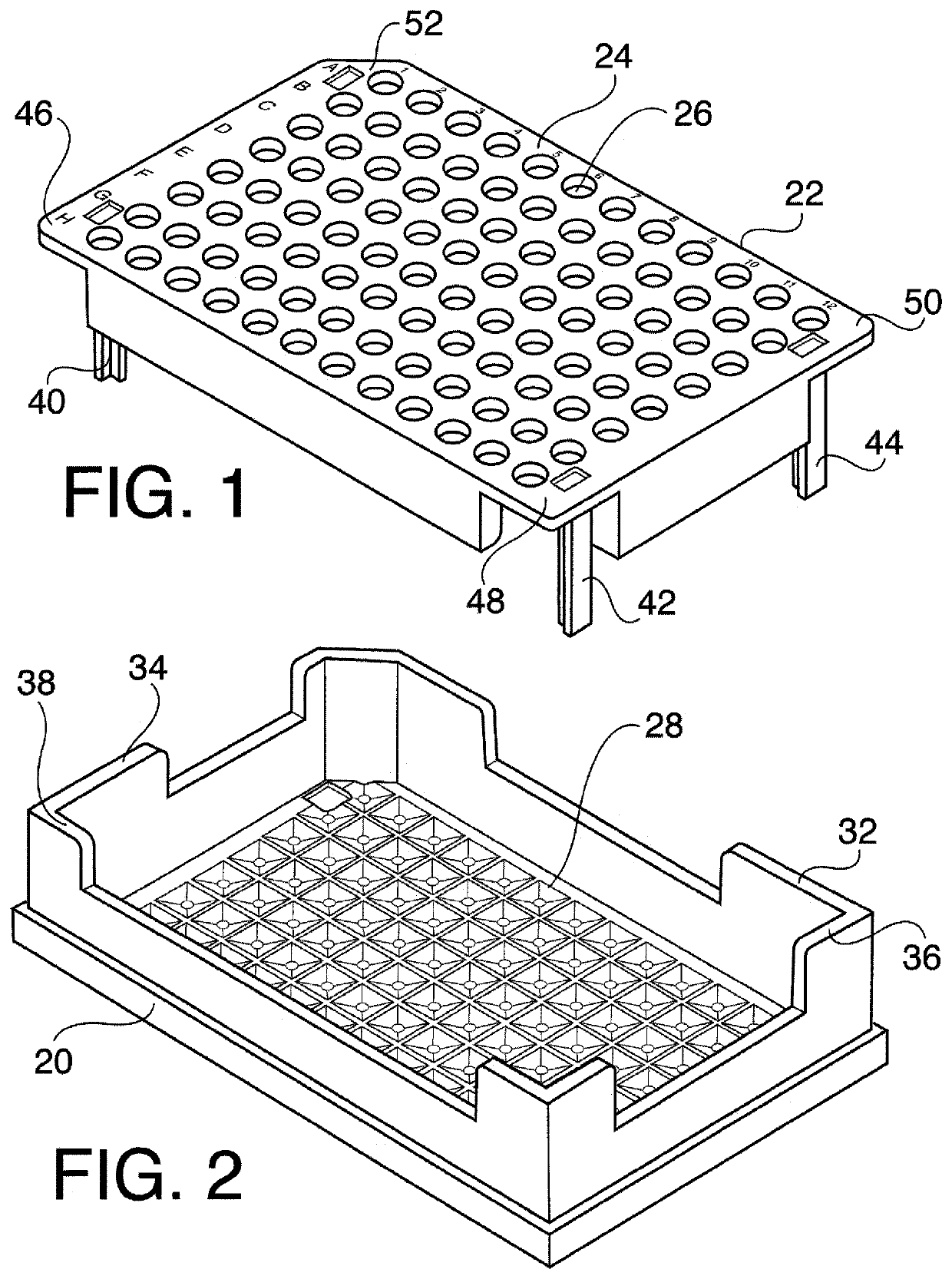
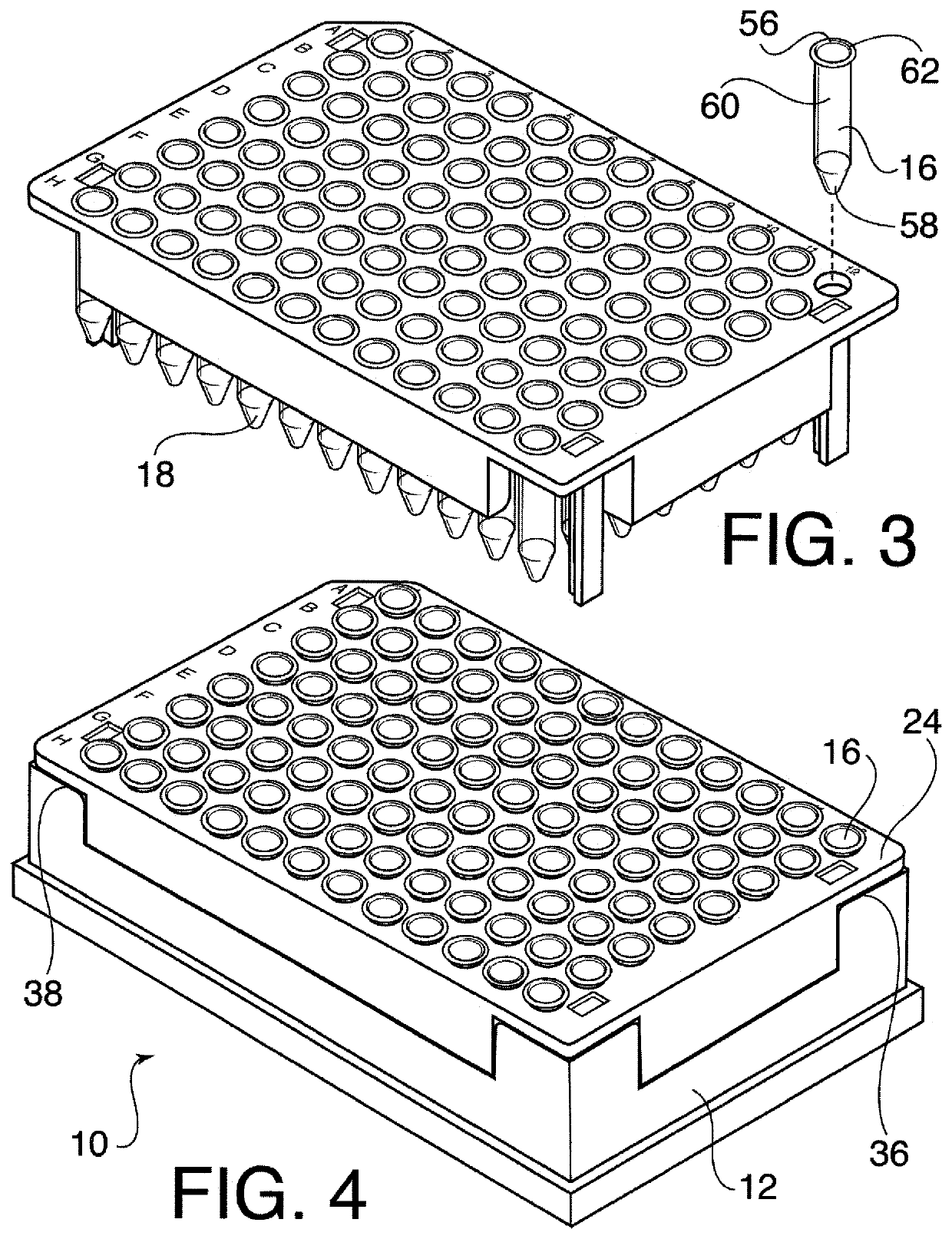
[0020]Referring now to the drawings in detail wherein like reference numerals have been used throughout the various figures to designate like elements, there is shown in FIG. 4 a split microplate and vials constructed in accordance with the principles of the present invention and designated generally as 10.

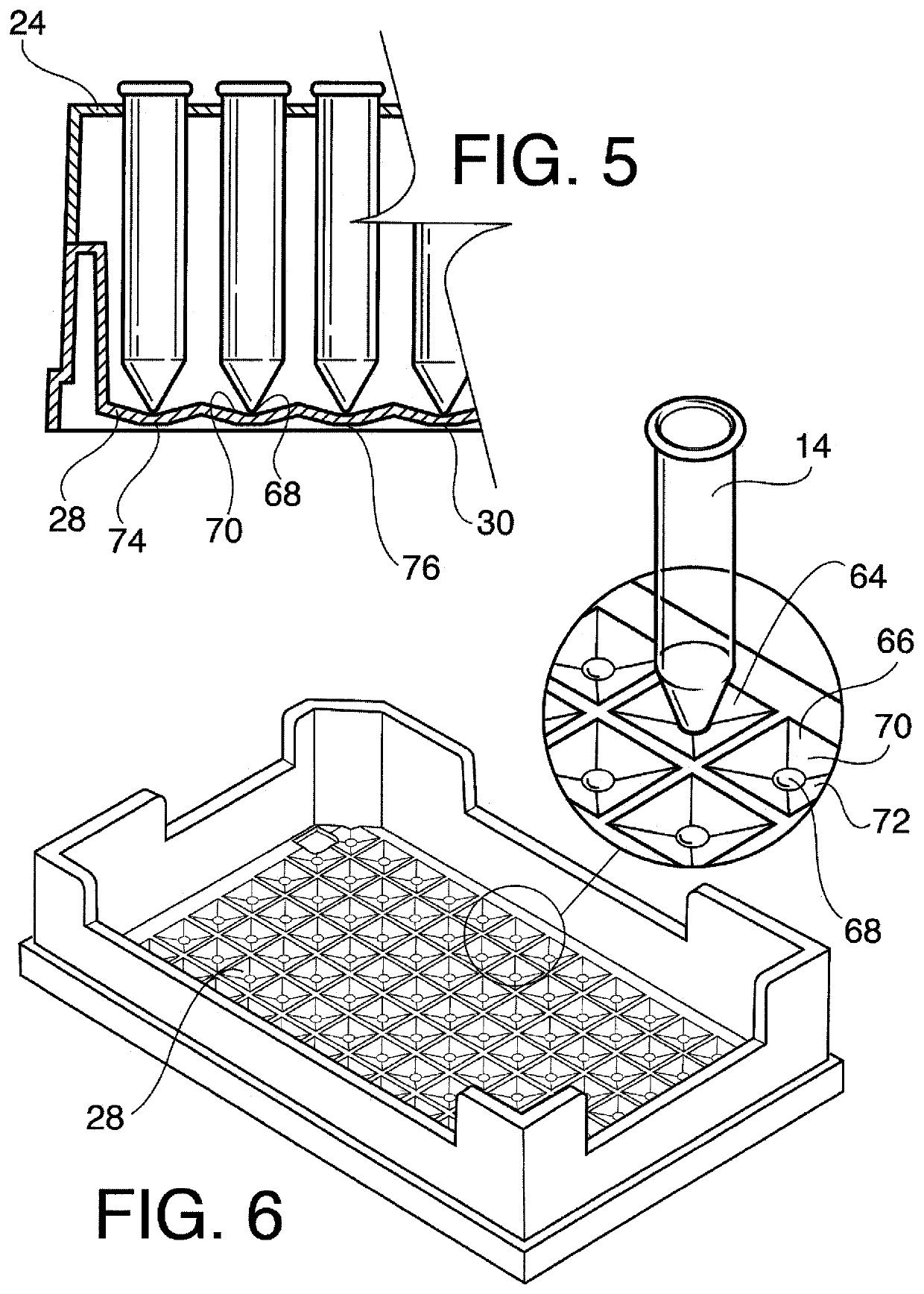
[0021]The split microplate and vials 10 is comprised essentially of two parts, the microplate 12 and the plurality of vials such as shown at 14, 16 and 18. The microplate itself is also comprised of two parts: a base 20 as shown best in FIG. 2 and a rack 22 as best shown in FIG. 1.

[0022]The rack 22 has a top planar surface 24 with a plurality of openings 26 therein. In the preferred embodiment of the invention, there are 96 such openings 26. This is, however, only the preferred embodiment of the invention as a different number of openings 26 may be provided depending on the equipment in which the microplate is intended to be used.

[0023]The base 20 includes an interior bottom surfa...


PUM


Abstract

A split or two-part microplate is formed of a base and a rack. The rack has a top with a plurality of openings capable of holding glass vials. The base has an interior bottom surface and an exterior bottom surface and a plurality of upwardly extending vertical walls and being so dimensioned and sized so as to fit onto the base with at least a portion of the top planar surface resting on the vertical walls. When the rack is assembled onto the base, the top planar surface is spaced from the bottom surface by a first distance. The rack includes downwardly extending legs that are adapted to rest on a flat surface whereby the top planar surface is spaced from the flat surface by a second distance which is greater than the first distance. A plurality of vials is held in the openings and include rims preventing the vials from passing through the openings. The length of the vials from below the rim to the bottom is greater than the first distance but less than the second distance. Whereby, when the rack is resting on a flat surface, the vials hang from the rack and when the rack is assembled onto the base, the bottoms of the vials engage the interior bottom surface and the rims of the vials are positioned above the top planar surface.

Description

BACKGROUND OF THE INVENTION[0001]The present invention is directed toward the combination of a plurality of vials and a microplate and, more particularly, toward the combination of vials and a microplate wherein the microplate is split into two separate parts.[0002]As is well known in the art, microplates are widely used for storing, filtering, incubating and detecting samples in chemical experiments, biological assays, medical tests and the like. For example, a microplate might be used as micro-containers to store, filter, prepare, or incubate multiplicate samples in different wells. A microplate can also be used to conduct relatively tiny volume cell cultures in vitro. The sample filled microplate might eventually be subject to specific measuring methods to analyze its contents qualitatively and / or quantitatively in chromatographic or spectrometry systems.[0003]Some microplates, and primarily those made of plastic, have the wells formed directly therein. Others include openings in...

Claims


Application Information

Patent Timeline
Patent Type & Authority Applications(United States)
IPC IPC(8): B01L9/06
CPCB01L9/06B01L2300/0851B01L2300/0809B01L2300/0832
Inventor LODGE, DANIEL A.CONCORDIA, DAVID G.
Owner QIS INC
Learn More