Sorting facility

a sorting facility and sorting technology, applied in the direction of sorting, conveyor parts, control devices of conveyors, etc., can solve the problem of insufficient sorting of objects to be conveyed by the conveyance carriages

Active Publication Date: 2021-07-08
DAIFUKU CO LTD
View PDF0 Cites 0 Cited by
  • Summary
  • Abstract
  • Description
  • Claims
  • Application Information

AI Technical Summary

Benefits of technology

[0007]It is an object of the present invention to provide a sorting facility capable of causing a sorting section provided on the conveyance carriage to operate reliably in a predetermined position of a conveyance path.
[0017]According to the sorting facility of the present invention, the sorting section is instructed to start the sorting operation of the object to be conveyed at the timing when the first carriage detection section detects the conveyance carriage identified by the control section based on the position of the conveyance carriage managed by the position management section. Accordingly, even when a deviation occurs between the position of the conveyance carriage managed by the position management section, and the position of the conveyance carriage actually traveling on the conveyance path, it is possible to make an instruction to the sorting section at the same timing in the predetermined position. Accordingly, the sorting section can sort the object to be conveyed reliably in the sorting position, regardless of presence or absence of the deviation of the position of the conveyance carriage managed by the position management section.

Problems solved by technology

Therefore, the control section on the ground side cannot drive the belt conveyor (sorting section) provided on the conveyance carriage in a predetermined position of the conveyance path, and there is a problem of being unable to sort objects to be conveyed by the conveyance carriages sufficiently.

Method used


Image

  • Sorting facility
  • Sorting facility
  • Sorting facility

Examples


Embodiment Construction

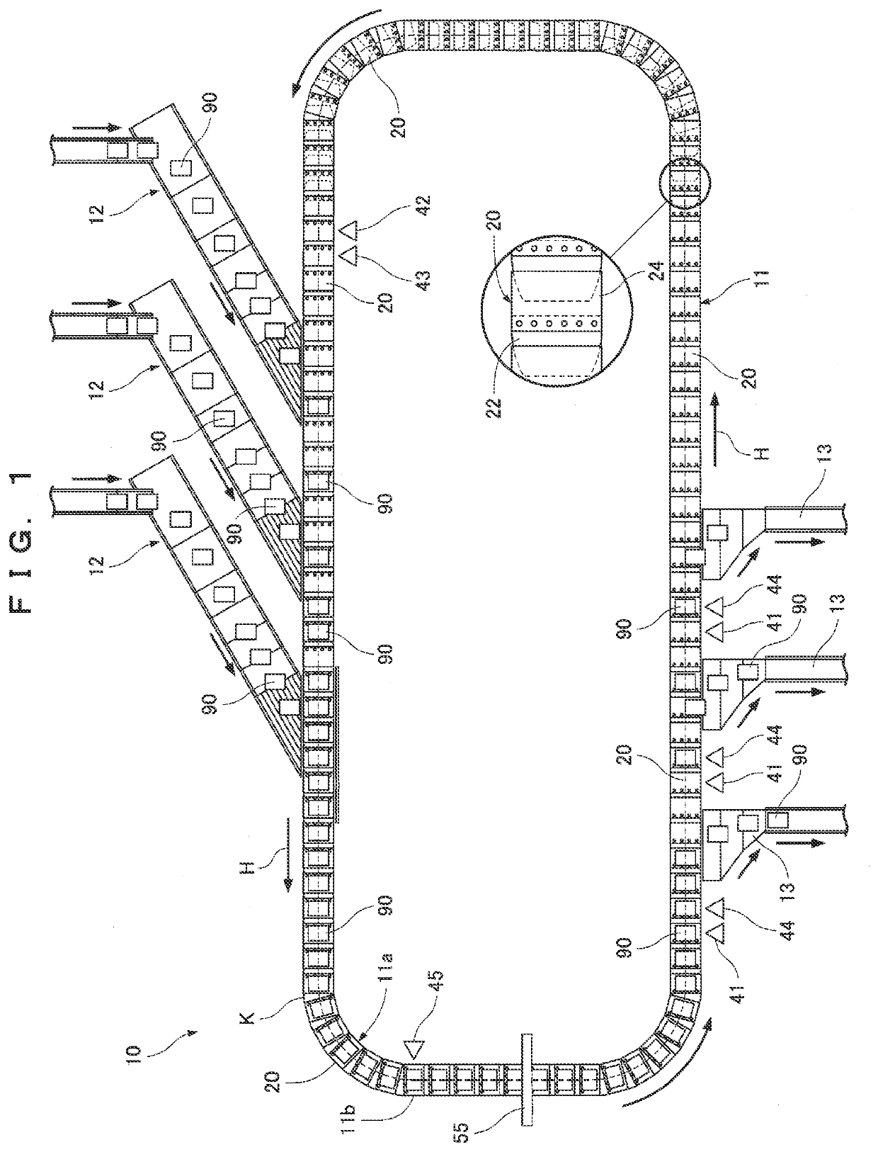
[0021]Sorting facility 10 of the present invention will be described. The present invention is not limited to the sorting facility 10 shown as follows.

[0022]As illustrated in FIG. 1, in the sorting facility 10, a loop-shaped conveyance path K for conveying articles 90 (example of “objects to be conveyed”) is formed. The sorting facility 10 is mainly composed of a main conveyor device 11 conveying the articles 90 along the conveyance path K, a plurality of induction conveyors 12 inputting the articles 90 onto the conveyance path K of the main conveyor device 11, a plurality of chutes 13 receiving the articles 90 delivered from the conveyance path K of the main conveyor device 11, and an article detection device 55 detecting a placement location of the article 90 on a belt conveyor 23.

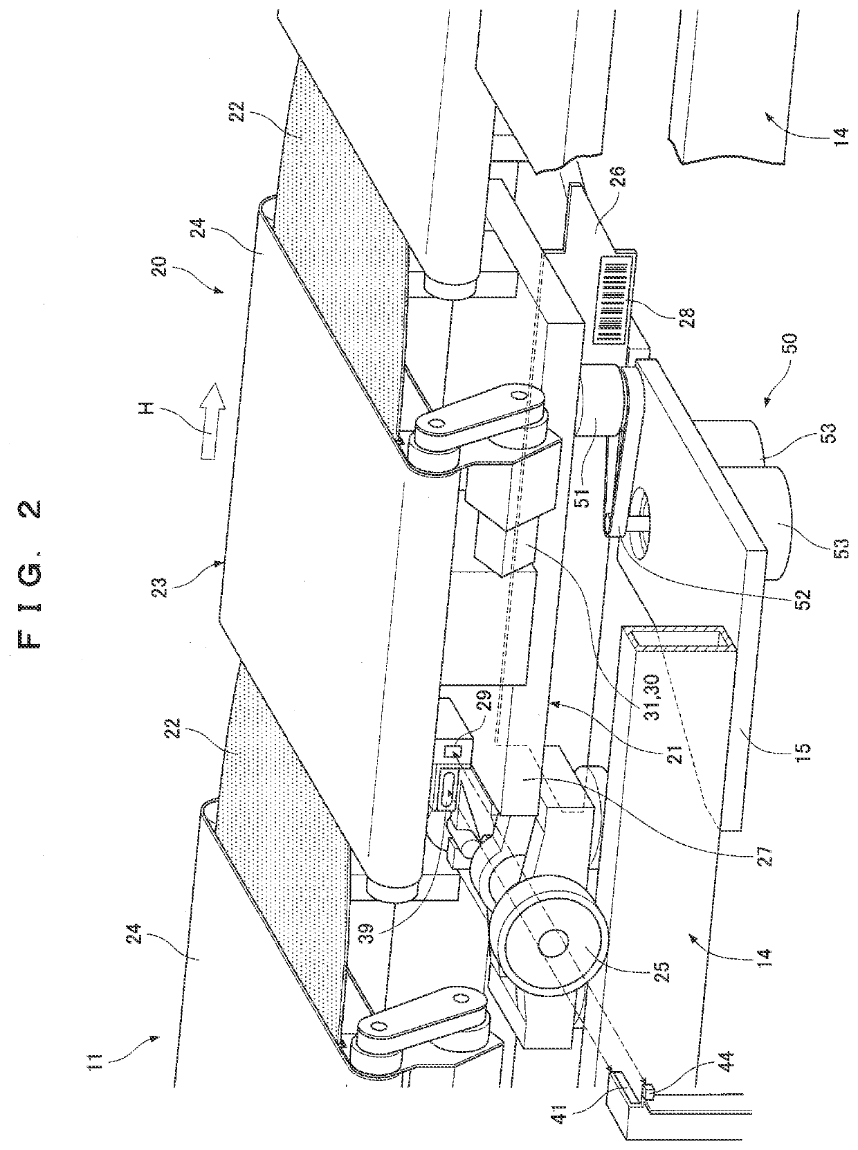
[0023]As illustrated in FIGS. 1 and 2, in the sorting facility 10, the article 90 is inputted to the conveyance carriage 20 traveling along rails 14 of the main conveyor device 11 from a predetermined in...


PUM


Abstract

A sorting facility for sorting articles by a plurality of connected conveyance carriages. The sorting facility includes a supervisory controller managing a position of each of the conveyance carriages, a trigger sensor detecting each of the conveyance carriages, and a belt conveyor provided on each of the conveyance carriages. The supervisory controller identifies each of the conveyance carriages that should deliver the articles to the chute based on the managed position of each of the conveyance carriages. The supervisory controller instructs the belt conveyor provided in each of the conveyance carriages identified to start a delivery operation of each of the articles at timing when each of the conveyance carriages identified is detected by the trigger sensor.

Description

FIELD OF THE INVENTION[0001]The present invention relates to sorting facility connecting a plurality of conveyance carriages conveying objects to be conveyed along a conveyance path, and sorting the objects to be conveyed by loading the objects to be conveyed onto the conveyance carriages or delivering the objects to be conveyed from the conveyance carriages, in a sorting position formed in a predetermined position of the conveyance path.BACKGROUND OF THE INVENTION[0002]Conventionally, there has been sorting facility as shown in Japanese Patent Laid-Open No. 2018-122988, as the sorting facility sorting objects to be conveyed by running a plurality of connected conveyance carriages along the conveyance path.[0003]The sorting facility in Japanese Patent Laid-Open No. 2018-122988 sorts articles by running a plurality of conveyance carriages connected endlessly along a loop-shaped conveyance path. The conveyance carriages traveling on the conveyance path receives articles in the belt co...

Claims


Application Information

Patent Timeline
Patent Type & Authority Applications(United States)
IPC IPC(8): B65G43/08B65G17/12B07C3/08
CPCB65G43/08B65G17/12B65G47/44B65G2203/0283B07C3/082B65G47/52B65G43/00B07C5/36B65G47/96
Inventor UEDA, YUICHIMATSUI, OSAMUKOIDE, HIROYUKIISHIKURA, ATSUSHI
Owner DAIFUKU CO LTD
Why Eureka
Try Eureka