Apparatuses and methods for adjusting a therapeutic electrical dose

a technology of electrical dose and electrical device, which is applied in the field of implantable neuromodulators, can solve the problems of pain and/or discomfort for patients, difficulty in determining the optimal dosage at which the applied voltage is applied, and achieve the effect of high scoring change in patient-reported pain levels

Pending Publication Date: 2021-07-22
NEUROS MEDICAL
View PDF0 Cites 3 Cited by
  • Summary
  • Abstract
  • Description
  • Claims
  • Application Information

AI Technical Summary

Problems solved by technology

In the absence of the teachings described herein, it is difficult to determine an optimal dosage at which the applied voltage is increase to a peak and sustained for sufficiently long to achieve a therapeutic benefit.
The inventors have found that although it is generally beneficial to apply as high a voltage as possible to the patient, particularly (but not exclusively) in applications in which neural modulation comprises high-frequency (e.g., greater than 1 kHz) modulation from an implanted neuromodulator to inhibit activity of a nerve or nerve bundle, there is a difficulty to define voltage threshold, above which further voltage amplitude may result in pain and / or discomfort for the patient.

Method used


Image

  • Apparatuses and methods for adjusting a therapeutic electrical dose
  • Apparatuses and methods for adjusting a therapeutic electrical dose
  • Apparatuses and methods for adjusting a therapeutic electrical dose

Examples


example structures

and Systems

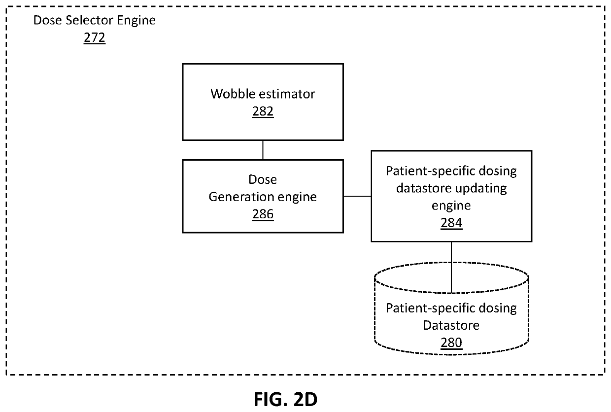
[0078]FIG. 2C is a diagram showing an example of a neuromodulation system that include dose setting as described above 270A. The modules of the neuromodulation system 270A may include one or more engines and datastores. A computer system can be implemented as an engine, as part of an engine or through multiple engines. As used herein, an engine includes one or more processors or a portion thereof. A portion of one or more processors can include some portion of hardware less than all of the hardware comprising any given one or more processors, such as a subset of registers, the portion of the processor dedicated to one or more threads of a multi-threaded processor, a time slice during which the processor is wholly or partially dedicated to carrying out part of the engine's functionality, or the like. As such, a first engine and a second engine can have one or more dedicated processors or a first engine and a second engine can share one or more processors with one another o...


PUM


Abstract

Apparatuses and methods of using them for setting a therapeutic dose of a neuromodulator implanted into a patient are described. The methods and apparatuses described herein may include determining the dose based on a patient-specific database of previously delivered dose parameters and corresponding pre-delivery and post-delivery pain estimates from the patient.

Description

CROSS REFERENCE TO RELATED APPLICATIONS[0001]This patent claims priority to U.S. provisional patent application No. 62 / 720,071, titled “APPARATUSES AND METHODS FOR ADJUSTING AN ELECTRICAL DOSE,” filed on Aug. 20, 2018, and is herein incorporated by reference in its entirety.[0002]This patent may be related to one or more of: U.S. patent application Ser. No. 15 / 510,824, titled “NERVE CUFF ELECTRODE FOR NEUROMODULATION IN LARGE HUMAN NERVE TRUNKS” and filed on Sep. 12, 2014, which claims priority to U.S. patent application Ser. No. 14 / 276,200 (now U.S. Pat. No. 8,983,612) filed May 13, 2014; which is a continuation of U.S. patent application Ser. No. 13 / 474,926 filed May 18, 2012 now U.S. Pat. No. 8,731,676; which claims priority to U.S. patent application Ser. No. 61 / 487,877 filed May 19, 2011, each of which is expressly incorporated by reference herein in its entirety.INCORPORATION BY REFERENCE[0003]All publications and patent applications mentioned in this specification are herein ...

Claims


Application Information

Patent Timeline
Patent Type & Authority Applications(United States)
IPC IPC(8): A61N1/06A61N1/36A61N1/05A61N1/372
CPCA61N1/06A61N1/36153A61N1/36071A61N1/37247A61N1/36171A61N1/0551A61N1/36146A61N1/0556A61B5/4824
Inventor FANG, ZI-PINGSYED SHAH, NEMATHIORIO, MATTHEW J.
Owner NEUROS MEDICAL
Why Eureka
Try Eureka