
Printer for printing a cable marker strip, and cable marker strip for the same

a technology for printing and cable markers, applied in the field of cable markers, can solve the problems of difficulty in reading the labelling on the adhesive tape, which usually fades very quickly, and the adhesive tape can dissolve and be lost, and achieve the effect of quick and permanent printing

Active Publication Date: 2021-07-29
WEIDMULLER INTERFACE GMBH & CO KG
View PDF0 Cites 0 Cited by
  • Summary
  • Abstract
  • Description
  • Claims
  • Application Information

AI Technical Summary

Benefits of technology

The patent describes a fastening structure made of a heat-resistant and rigid plastic called polycarbonate and acrylonitrile butadiene styrene (PC-ABS), and a softer plastic called thermoplastic polyurethane (TPU). The labeling track is made of TPU for its pliability and ability to print on its entire surface. The patent also describes a method for quickly and permanently printing the labeling surface of one or multiple cable markers by arranging them side by side and using a printer. The labeling surface of the cable marker strip is designed to be labeled.

Problems solved by technology

The labeling is often done with a ballpoint pen, a pencil or a felt pen, and is therefore often difficult to read the labelling on the adhesive tape which usually fades very quickly.
In addition, the adhesive tape can dissolve and be lost, especially under the influence of heat.
This solution is unsuitable in a professional environment, for example in the assembly of control cabinets or in the context of production plants, because the labeling is very time-consuming, the marking is not sufficient and / or not permanently legible, and can even be lost.

Method used


Image

  • Printer for printing a cable marker strip, and cable marker strip for the same
  • Printer for printing a cable marker strip, and cable marker strip for the same
  • Printer for printing a cable marker strip, and cable marker strip for the same

Examples


Embodiment Construction

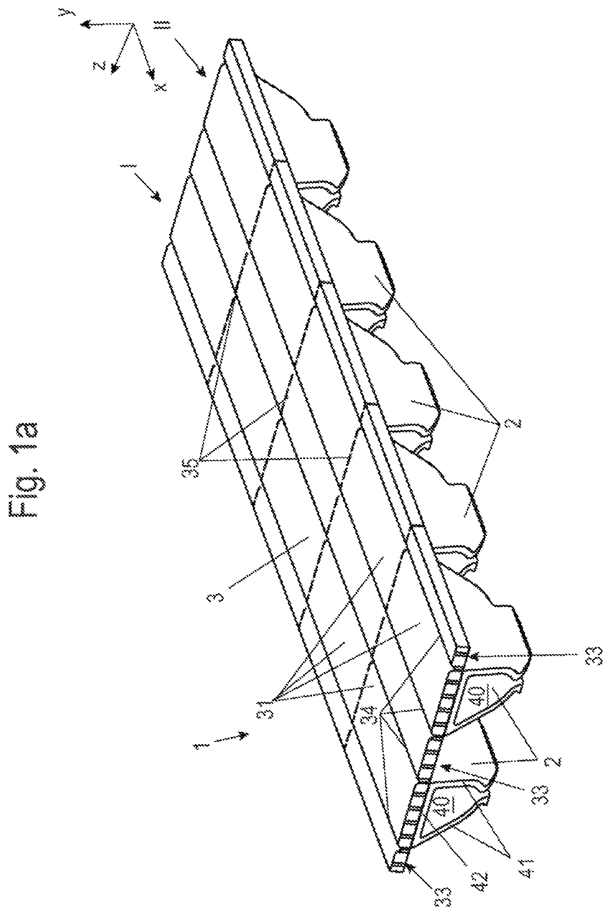
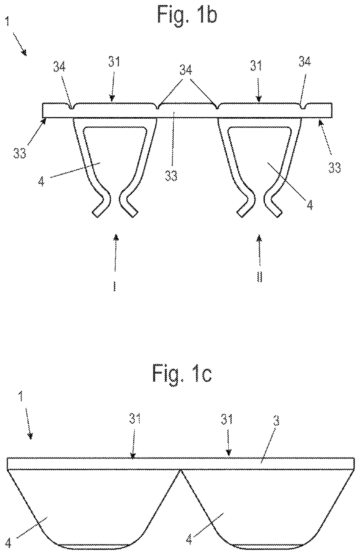
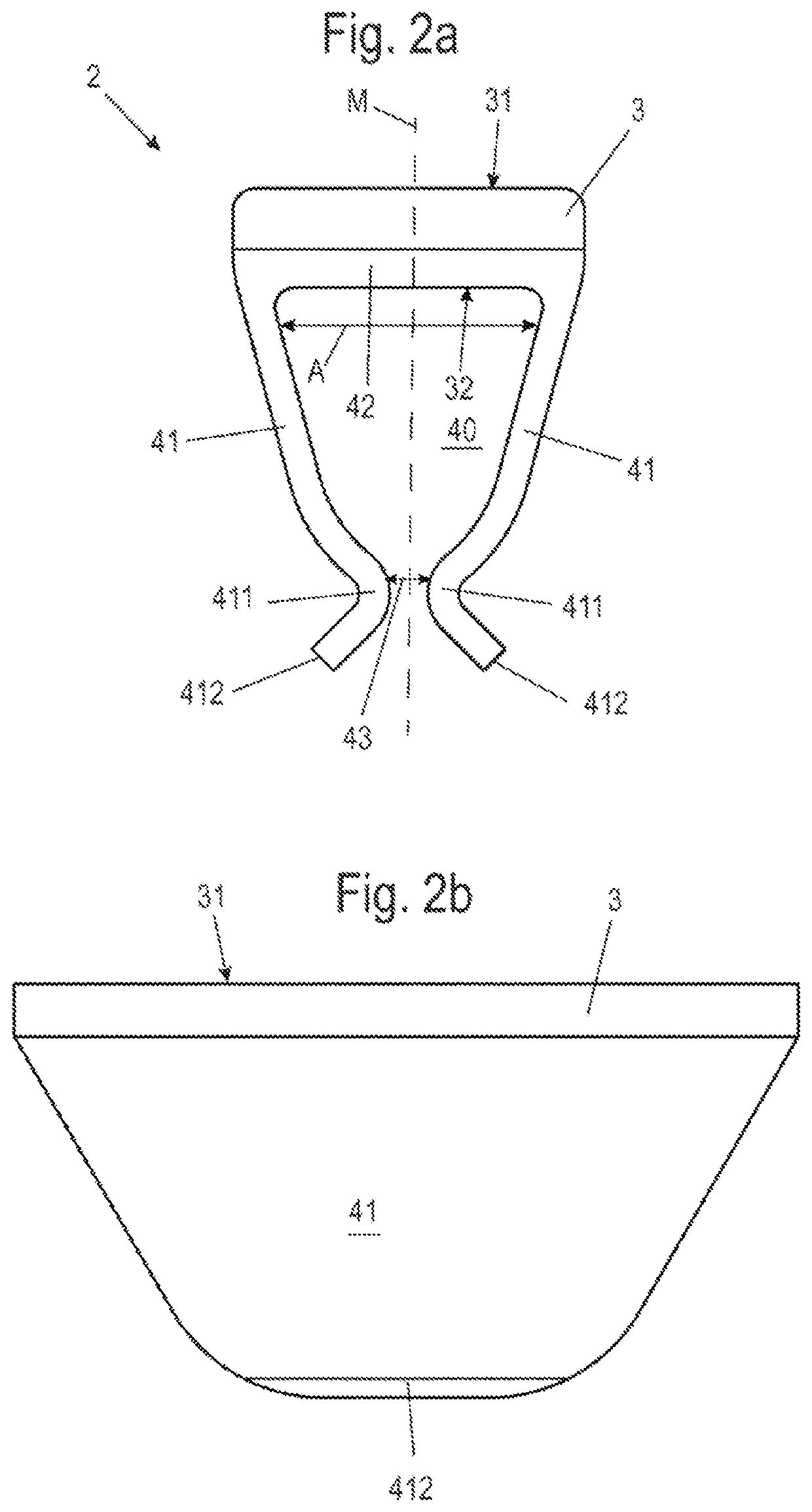
[0039]FIG. 1a shows a cable marker strip 1, which includes two rows I, II of cable markers 2 next to one another in arranged in the direction Z. FIG. 1b shows a front side of the cable marker strip 1 and FIG. 1c is a side view of such a cable marker strip 1 with two cable markers.

[0040]The cable marker strip 1 has a labeling track 3 which can be labeled and printed. The cable marker strip 1 extends in the cable direction X and has two rows I, II of cable markers 2 in the arranging direction Z transverse to the cable direction X. However, the invention also includes cable marker strips 1 with only one row of cable markers 2 and cable marker strips 1 with more than two rows I, II of cable markers 2.

[0041]Each cable marker 2 is associated with a labeling surface 31 on the labeling track 3, which labeling surface 31 is defined in the arranging direction z by notches 34. In addition, perforations 35 may be provided which are arranged one after another in the direction X, to separate the ...


PUM


Abstract

A cable marker strip includes two rows of cable markers which are arranged behind one another in a cable direction. The cable marker strip includes a labeling track which has one labeling surface for each cable marker, wherein one fastening structure is provided for each cable marker on a fastening surface of the labeling track. The fastening surface lies opposite the labeling surface and has a connecting track and two holding limbs which are connected to the connecting track, which lie opposite one another, and together define a cable receptacle. Starting from the connecting track, spacing the holding limbs from one another decreases in the region of the cable receptacle so that the cable receptacle tapers. A printer for printing the cable marker strip and a method for printing the cable marker strip by way of the printer are also provided. The printer includes a print head which is arranged above pressure bars for the rows of cable markers.

Description

[0001]This application is a § 371 National Stage Entry of International Patent Application No. PCT / EP2019 / 064630 filed Jun. 5, 2019. Application No. PCT / EP2019 / 064630 claims priority of DE 10 2018 114 397.4 filed Jun. 15, 2018. The entire content of these applications is incorporated herein by reference.BACKGROUND OF THE INVENTION[0002]The present invention relates to a cable marker strip with at least one, and preferably two, rows of cable markers which are arranged behind one another in a cable direction. The cable marker strip includes a labeling track which has in each case one labeling surface for each cable marker, wherein in each case one fastening structure is provided for each cable marker on a fastening surface of the labeling track. The fastening surface lies opposite the labeling surface, and the fastening structure has a connecting track and two holding limbs which are connected to the connecting track, which lie opposite one another, and together define a cable recepta...

Claims


Application Information

Patent Timeline
IPC IPC(8): G09F3/20B41J3/407G09F3/06
CPCG09F3/205G09F2003/0201G09F3/06B41J3/4075B41F17/00B41P2217/50
Inventor WIENEKE, ANDREASDAHLMANN, MARKUSDOGAN, FAYSAL
Owner WEIDMULLER INTERFACE GMBH & CO KG
Learn More