Radiation detector comprising a light reflective material

a light-reflective material and detector technology, applied in the field of radiation detectors, can solve the problems of white separators or spacers made by means of this known technology, the thickness of white coatings at the outside edge of arrays, and the limited space for coatings, so as to increase the scattering coefficient of resultant materials, reduce stress, and reduce the effect of scattering

Active Publication Date: 2016-11-08
KONINK PHILIPS ELECTRONICS NV
View PDF13 Cites 0 Cited by
  • Summary
  • Abstract
  • Description
  • Claims
  • Application Information

AI Technical Summary

Benefits of technology

[0018]The pliability of the resin provides good mechanical properties, and will allow the resin to change its size with temperature in conformity with the changes in the silicon chip without exerting substantial forces upon that chip. Differential thermal expansion of the detector components is thus allowed without generating large delamination forces. Moreover, the pliability will also allow assembly of the array upon the photo-detecting element array even when either of them is not absolutely flat, because they can be pressed together to conform.
[0034]According to an aspect of the invention, the light-reflecting element has a low refractive index of less than 1.5, and preferably less than 1.45. Such low values of the refractive index ensure that the problems of the prior art as described above are overcome in that it becomes possible to obtain a light-reflecting material having a scattering coefficient exceeding 4000 cm−1, which is twice the scattering coefficient of similar epoxy resins. A resin having a refractive index of 1.44 has turned out to be advantageous.

Problems solved by technology

However, problems exist in the known X-ray detector arrays.
As the X-ray detector arrays grow in size, thermal expansion problems between the stiff epoxy resin having a high coefficient of thermal expansion (CTE) and the fragile silicon chip having a low CTE may cause delamination, especially when the assembly suffers from extreme temperatures.
Moreover, white separators or spacers made by means of this known technology must be fairly thick.
Furthermore, white coatings at the outside edge of an array, where space for coatings is limited, must also be relatively thick.

Method used


Image

  • Radiation detector comprising a light reflective material
  • Radiation detector comprising a light reflective material
  • Radiation detector comprising a light reflective material

Examples


Embodiment Construction

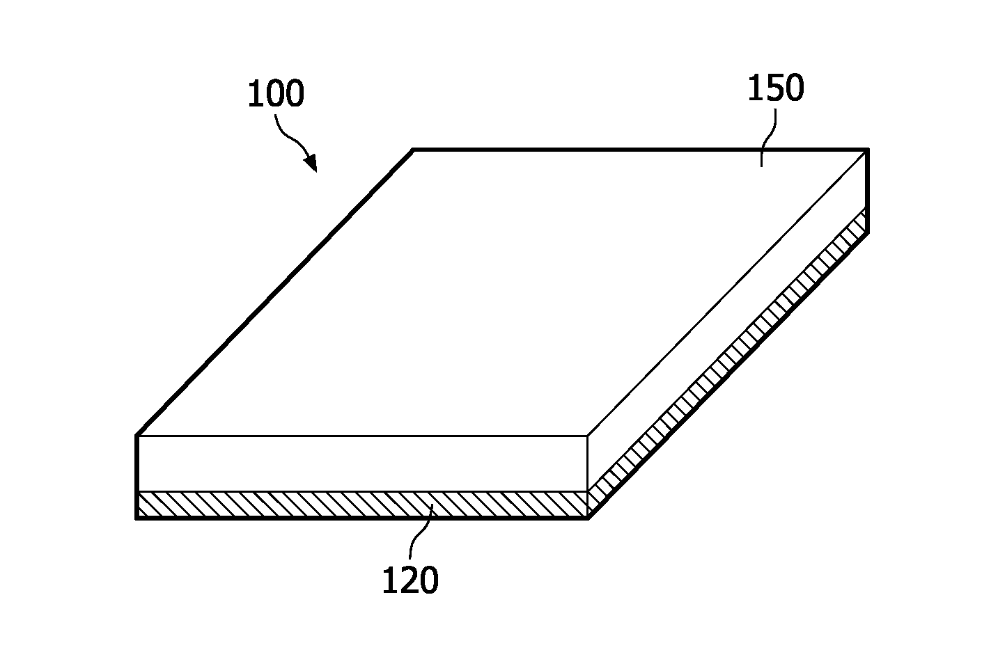
[0045]FIG. 1 is a perspective view of a radiation detector 100. The radiation detector 100 is an X-ray detector. The X-ray detector 100 comprises a photo-detecting element array 120 having one or more photo-detecting elements. The photo-detecting elements may be photodiodes or any other material converting light to electricity. The detector 100 also comprises imaging elements in the form of a scintillation layer 150 comprising one or more scintillator elements. The scintillator elements of the scintillation layer 150 are covered by a light-reflecting material. FIG. 1 shows that the scintillation layer 150 is arranged above and fixed to the photo-detecting element array 120. The scintillation layer may be optically coupled to the front or top surface of the photo detector array using an optical adhesive. In FIG. 1, the components of the scintillation layer, viz. the scintillator elements, are covered and concealed by the light-reflecting material.

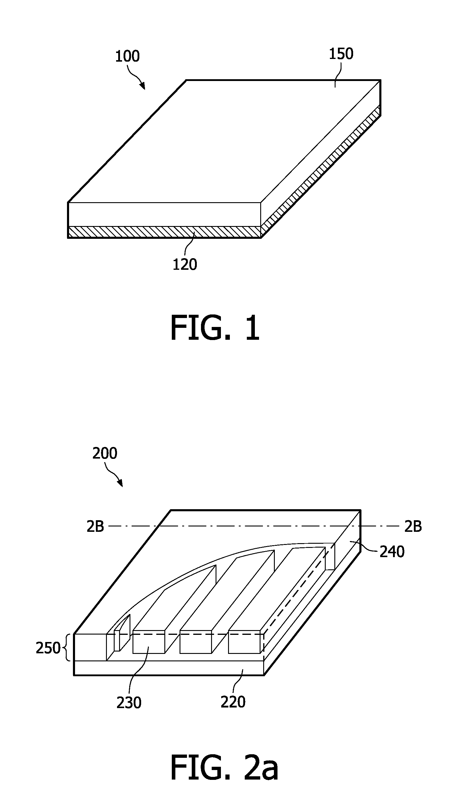
[0046]FIG. 2a is a perspective view o...


PUM


Abstract

A light-reflecting material of a radiation detector, which also comprises photo-detecting elements and imaging elements adjacent to the photo-detecting elements, is provided. Typically, epoxy resin is used as the light-reflecting material. A tough, pliable resin may be used for the photo-detecting elements. This has the advantage of reducing thermal stresses inside the radiation detector, thus reducing the risk of delamination due to e.g. temperature shifts. Moreover, the tough, pliable resin preferably also has a low refractive index, which may increase the scattering co-efficient of the resin as compared to epoxy resin, which has a refractive index of 1.58. The layer thickness of a low-refractive index resin may thereby be reduced as compared to the layer thickness of epoxy resin for a given level of optical crosstalk. Preferable resins are silicon resins and resins of thermoplastic fluoropolymers.

Description

FIELD OF THE INVENTION[0001]The present invention relates to a radiation detector and use of light-reflecting material in a radiation detector.BACKGROUND OF THE INVENTION[0002]Radiation detectors are particularly used in computed tomography (CT) scanners and will be described with particular reference thereto. However, the invention also finds use in DF (diffraction) and RF (radio frequency) imaging, X-ray fluoroscopy, radiography, and other examination systems for medical and non-medical examinations.[0003]Computed tomography (CT) imaging typically employs an X-ray source that generates a beam of X-rays traversing an examination area. A subject arranged in the examination area interacts with and absorbs a portion of the traversing X-rays. A two-dimensional radiation detector including an array of detector elements is arranged opposite the X-ray source to detect and measure intensities of the transmitted X-rays.[0004]Typically, the X-ray source and the radiation detector are mounted...

Claims


Application Information

Patent Timeline
Patent Type & Authority Patents(United States)
IPC IPC(8): G01T1/24G01T1/20
CPCG01T1/2018G01T1/2002G01T1/20183G01T1/20185
Inventor LEVENE, SIMHAWAINER, NAOR
Owner KONINK PHILIPS ELECTRONICS NV
Why Eureka
Try Eureka