A method of operating an automated storage and retrieval system

a technology of automated storage and retrieval system, applied in the direction of stacking articles, process and machine control, instruments, etc., can solve the problems of delayed delivery, inconvenient operation, and inability to know the position of the container handling vehicle with certainty, so as to achieve efficient and smooth movement

Pending Publication Date: 2021-08-05
AUTOSTORE TECH AS
View PDF0 Cites 0 Cited by
  • Summary
  • Abstract
  • Description
  • Claims
  • Application Information

AI Technical Summary

Benefits of technology

[0043]Thus, the invention allows for more efficient and faster queuing of container handling vehicles accessing a target cell, as the first container handling vehicle does not have to wait for the second handling vehicle to transmit its new cell position to the central control unit, and / or for the central control unit to process this information and then command the first container handling vehicle to move into the target cell. The invention may be especially advantageous where container handling vehicles are operating on a rail system in the vicinity of port columns, and where container handling vehicles comprising container delivery vehicles are operating on a rail system for delivery of storage containers to be picked at an access point. The invention may be especially advantageous where the target cell is free, or it is considered acceptable for the first container handling vehicle to start moving into the target cell, but it would not move in the prior art as it requires a command to do so from the central control unit. The invention may therefore allow the first container handling vehicle to start moving towards the target cell whilst the second container handling vehicle is still partially within the target cell. The invention may also provide a more efficient use of bandwidth in the automated storage system, as unnecessary signals back and forth between the central control unit and the container handling vehicles are reduced. The processing power of the central control unit may also be used more efficiently as the first container handling vehicle does not require a separate command to move into the target cell when the control unit has computed that it is free, as is necessary in the prior art.
[0047]The invention may thus be advantageous where container delivery vehicles operate on a rail system, as these rails systems can become heavily trafficked. The target cell may be defined as a cell to which the first container handling vehicle has received a command to move to. A plurality of container handling vehicles may form queues, which may be typical around port cells. In such cases the invention may provide a more efficient and smooth movement of the container handling vehicles as access to the port cell is freed up and the first container handling vehicle in the queue moves in to the cell, whilst the other vehicles follow closely by the method disclosed herein, which allows them to move towards a target cell whilst another vehicle is still partially in the target cell.
[0048]The vehicle control system of the first container handling vehicle may derive which parts of the proximity sensor system require activation based on the command it receives from the central control system, which typically may be the part of the proximity sensor system arranged to measure in the direction in which the first container handling vehicle is commanded to drive to reach the target cell. In other aspects, the central control system may include instructions in the data signal as to which parts of the proximity sensor system is to be activated. The vehicle control system may further receive instructions in the data signal regarding the duration of activation for the proximity sensor system, which may depend on whether the first container handling vehicle is following the second container handling vehicle in a parallel direction, or the second container handling vehicle moves in an orthogonal direction. It may for example be advantageous to keep the proximity sensor system activated when the first container handling vehicle follows the second container handling vehicle to avoid collisions.
[0058]The method may comprise continuously monitoring with the proximity sensor system of the first container handling vehicle as it moves into the target cell to detect if the second container handling vehicle is within a predetermined distance. Thus, the first container handling vehicle may monitor whether the second container handling vehicle unexpectedly stops, such that it may itself stop moving and avoid a collision. Continuous monitoring may thus be advantageous when the container handling vehicles move in the same or a parallel direction. The data signal transmitted to the first container handling vehicle may thus command it to continuously monitor the predetermined distance in its direction of travel.

Problems solved by technology

A problem associated with known traffic flow management is that the area surrounding certain cells, such as ports 19, 20 or other columns frequently visited by container handling vehicles, may become congested with the container handling vehicles 101 instructed to drop off or pick up storage containers 106.
A problem with the prior art is that the position of a container handling vehicle is not known with certainty until it has passed a track crossing.
This results in a delay due to the command being relayed through, and processed in, the central control system.
Moreover, delays will occur in situations where access to the target cell 12 is free, but the formerly blocking container handling vehicle has not yet established and transmitted its new position.
Furthermore, the relaying of this information takes up limited capacity on the communications bandwidth between the container handling vehicles 101 and the control system.

Method used


Image

  • A method of operating an automated storage and retrieval system
  • A method of operating an automated storage and retrieval system
  • A method of operating an automated storage and retrieval system

Examples


Embodiment Construction

[0115]In the following, embodiments of the invention will be discussed in more detail by way of example only and with reference to the appended drawings. It should be understood, however, that the drawings are not intended to limit the invention to the subject-matter depicted in the drawings.

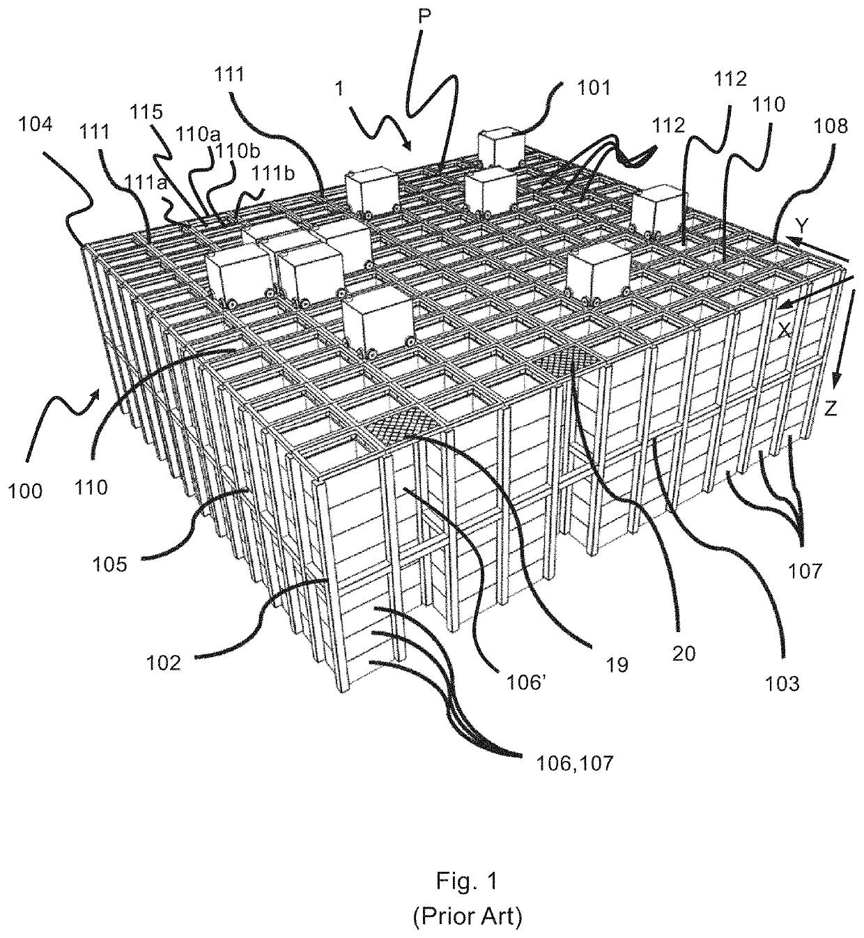
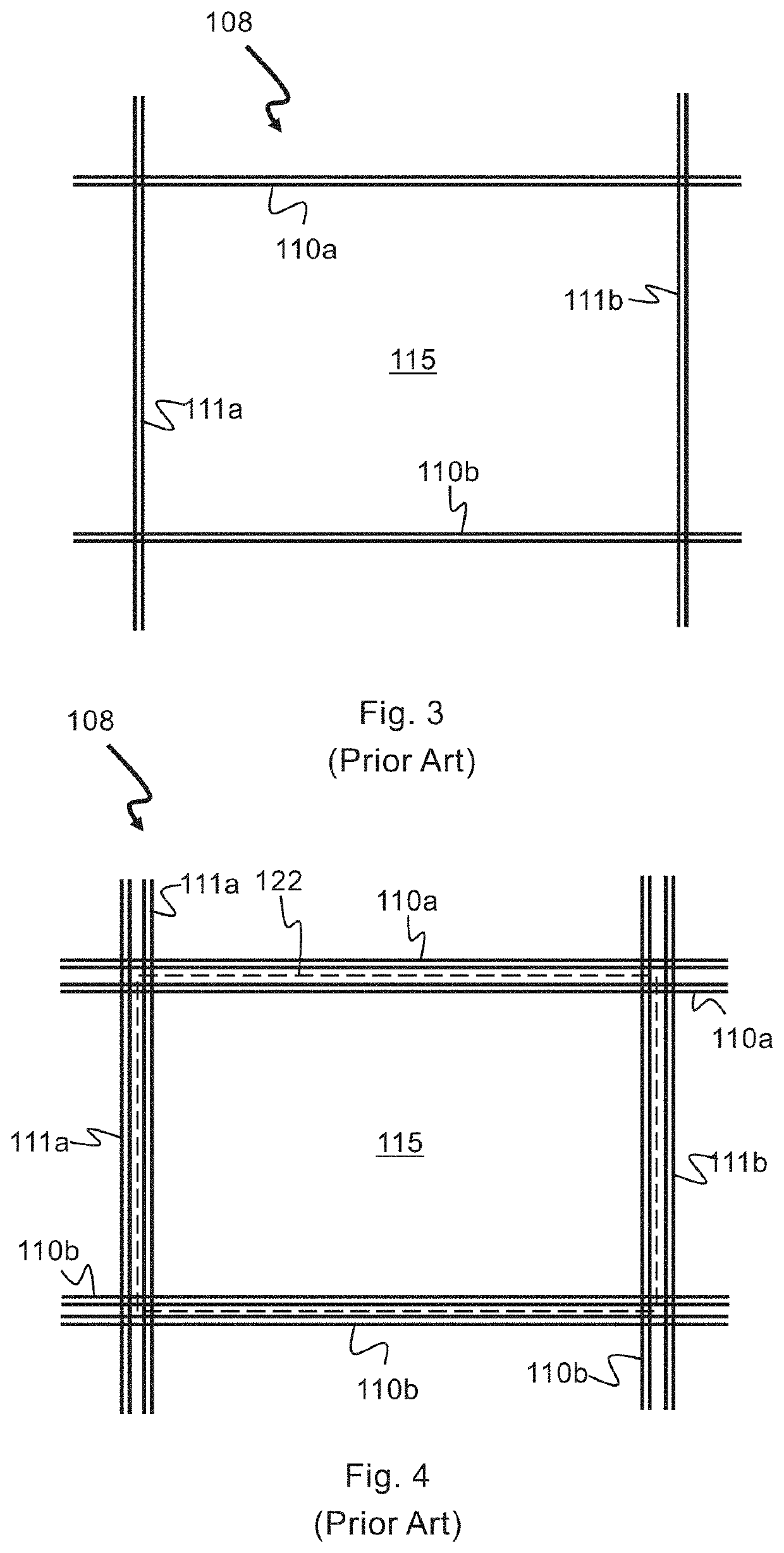
[0116]The framework 100 of the automated storage and retrieval system 1 is constructed in accordance with the prior art framework 100 described above in connection with FIGS. 1-4, i.e. a number of upright members 102 and a number of horizontal members 103, which are supported by the upright members 102, and further that the framework 100 comprises a rail system 108 of parallel rails 110,111 in X direction and Y direction arranged across the top of storage columns 105 / grid columns 112. The horizontal area of a grid column 112. i.e. the area along the X and Y directions, may be defined by the distance between adjacent rails 110 and 111, respectively (see FIGS. 3 and 4).

[0117]In FIG. 1 the grid 104...


PUM


Abstract

A method of operating an automated storage and retrieval system includes: a rail system including a first set of parallel rails arranged in a horizontal plane and extending in a first direction, and a second set of parallel rails arranged in the horizontal plane and extending in a second direction which is orthogonal to the first direction, which first and second sets of rails form a grid pattern in the horizontal plane including a plurality of adjacent grid cells, a central control unit configured to receive, transmit and process data signals of a plurality of container handling vehicles for handling storage containers of the automated storage and retrieval system. Each container handling vehicle includes a vehicle body, a wheel assembly provided on the vehicle body, the wheel assembly being configured to move the vehicle along the rail system in both of the first direction and the second direction, a vehicle control unit configured to receive data signals from, transmit data signals to and process data signals of the central control unit, and a proximity sensor system configured to detect another container handling vehicle of said plurality of container handling vehicles and determine whether or not it is within a predetermined distance. The method includes detecting with the central control unit that access of a first container handling vehicle to a target cell, which is one of the plurality of grid cells, is blocked by a second container handling vehicle, transmitting a data signal from the central control unit to the vehicle control unit of the first container handling vehicle commanding the first container handling vehicle to move into the target cell when the second container handling vehicle is beyond said predetermined distance.

Description

TECHNICAL FIELD[0001]The present invention relates to a method of operating an automated storage and retrieval system, and an automated storage and retrieval system.BACKGROUND AND PRIOR ART[0002]FIG. 1 discloses a typical prior art automated storage and retrieval system 1 with a framework structure 100 and FIGS. 2a and 2b disclose prior art container handling vehicles 101, 201 of such a system 1.[0003]The framework structure 100 comprises a plurality of upright members 102 and a plurality of horizontal members 103 which are supported by the upright members 102. The members 102, 103 may typically be made of metal, e.g. extruded aluminum profiles.[0004]The framework structure 100 defines a storage grid 104 comprising storage columns 105 arranged in rows, in which storage columns 105 storage containers 106, also known as bins, are stacked one on top of another to form stacks 107. Each storage container 106 may typically hold a plurality of product items (not shown), and the product ite...

Claims


Application Information

Patent Timeline
Patent Type & Authority Applications(United States)
IPC IPC(8): B65G1/04B65G43/00G05D1/02
CPCB65G1/0464B65G43/00G05D2201/0216B65G2203/0283B65G2203/042G05D1/0289B65G1/0414B65G1/0478B65G1/0485B65G1/0492B65G1/1378B65G2201/0235B65G1/065B65G1/0407B65G1/0471B65G63/06G05D1/0011G05D1/02G05D1/021G05D1/0229G05D1/0231G05D1/0259G05D1/0291B60W50/0098B60W2710/06B60W2720/10B60W2720/24B61B13/00B65G1/0457B65G1/1375B65G47/06B65G47/52B65G57/03B65G63/004B65G65/23B65G67/24B65G2201/0258B66F9/063B66F9/19
Inventor HEGGEBØ, JØRGEN DJUVEMÆHLE, OLE ALEXANDERMATRE, SYNNØVEFAGERLAND, INGVARSTUHAUG, RAGNAR
Owner AUTOSTORE TECH AS
Why Eureka
Try Eureka