Unlock instant, AI-driven research and patent intelligence for your innovation.

Tube fastener device

a technology of fasteners and tubes, which is applied in the direction of mechanical equipment, respirators, transportation and packaging, etc., can solve the problems of patient problems, complications, entanglement, confusion for medical staff, etc., and achieve the effect of reducing the translation of pulling force, increasing the resistance of pulling force, and minimising the crushing of tubing

Inactive Publication Date: 2021-08-12
THE COURT OF EDINBURGH NAPIER UNIV
View PDF1 Cites 2 Cited by
  • Summary
  • Abstract
  • Description
  • Claims
  • Application Information

AI Technical Summary

Benefits of technology

The patent text describes a device that prevents a tube from moving when it is pulled out of a device. This device allows for better management of the tube and reduces the risk of the tube being accidentally pulled out of the patient or ventilator. The device can also prevent the tube from moving relative to the patient. By using this device, patients can have more mobility and the ventilator can be moved around more easily.

Problems solved by technology

In all cases a sudden pull on the hollow tubing may cause medical complications; as such, it is necessary to secure the tubing and minimise pulling motions.
As stated, it is essential that once in place, the hollow tubing is securely fastened in position, and not for example accidentally pulled away: to do so could cause problems and complications for the patient.
Frequently a number of hollow tubes are provided to the patient, which can become entangled and confusing to medical staff at critical moments.

Method used


Image

  • Tube fastener device
  • Tube fastener device
  • Tube fastener device

Examples


Embodiment Construction

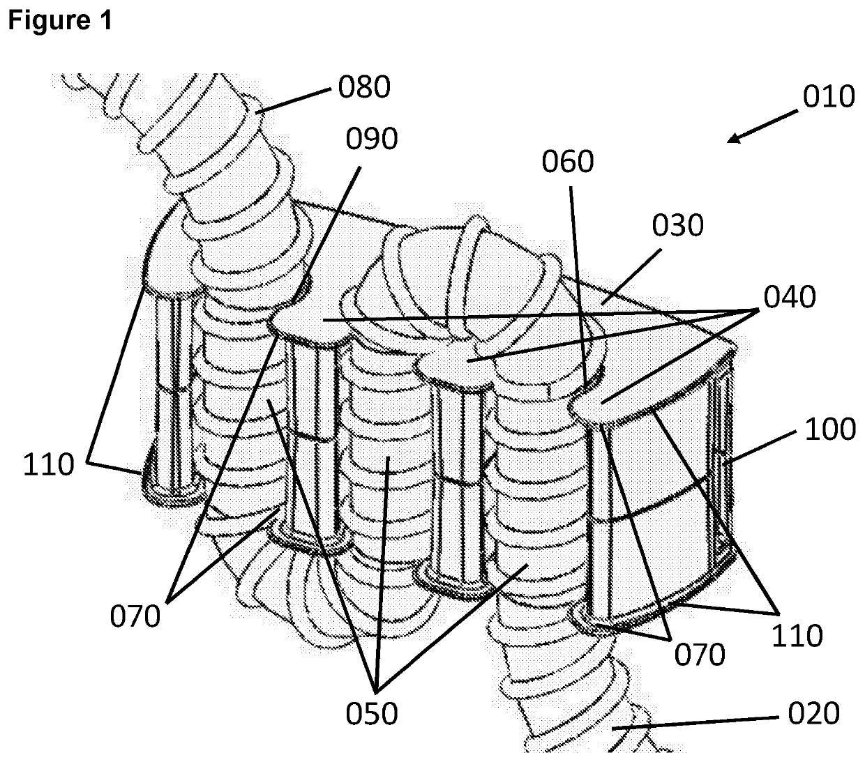
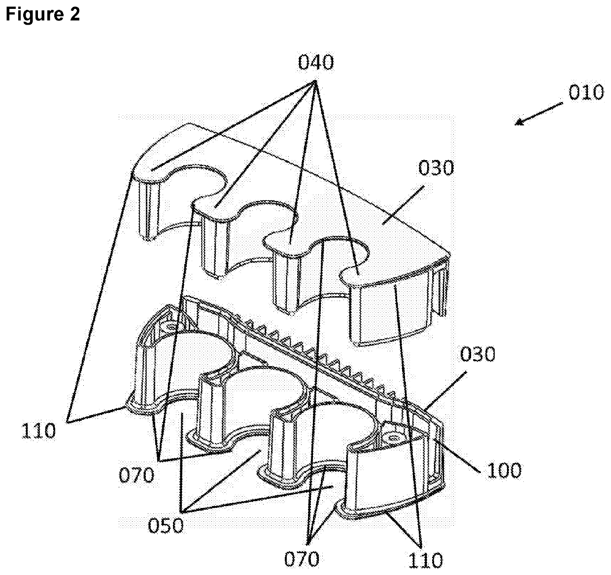
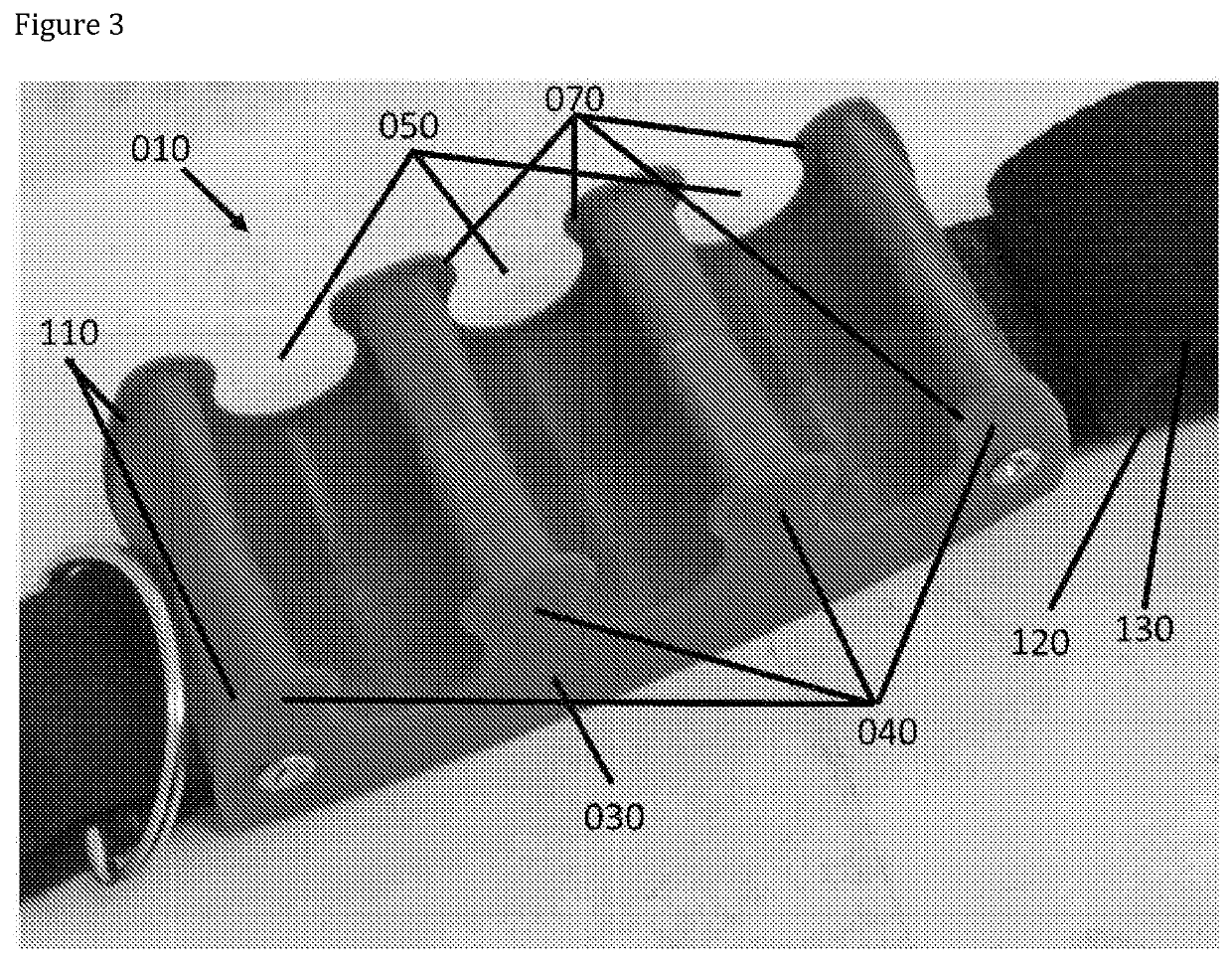
[0050]An embodiment of the invention is shown as an example in FIG. 1, where the device 010 is shown securing a portion of medical tubing 020. The device 010 comprises a body portion 030 comprised of at least one tube receiving portion 040 comprising one or more channels 050 (in this example three partially enclosed channels where the first and second channel are substantially parallel and the third channel is interposed between them) adapted to accommodate a portion of the tube to be held, where the surface provides a friction fit 060 to a tube when the tube is provided to the tube receiving portion of the device. In this embodiment the channels 050 further comprise friction inducing protrusions 070, in this case two flanges arranged at each end of the channels. In this embodiment the tube to be held 020 is a ventilator tube whose external surface comprises protrusions 080, in this case formed by a single helix. In this example the channel protrusions 070 are arranged to interlock ...


PUM

PropertyMeasurementUnit
Fractionaaaaaaaaaa
Lengthaaaaaaaaaa
Flexibilityaaaaaaaaaa

Abstract

There is described a tube fastener, in particular tube fastener to secure respiratory tubing for breathing systems, methods of using the tube fastener, a carriage for use with the tube fastener and a system.

Description

FIELD OF THE INVENTION[0001]This invention relates broadly to the field of tube fasteners and is particularly concerned with the securing of medical tubing with respect to a patient, suitably respiratory tubing for breathing systems.BACKGROUND TO THE INVENTION[0002]A key part of intensive medical care is the controlled delivery or removal of fluids, either gases or liquids to or from patients. In either case, the patient is connected to a dispensing or collecting means via hollow tubing or tubes which may be delicately attached at sensitive sites to the patient to permit fluid transference. For example, endotracheal tubing or tubes may be secured to a patient's neck to permit ventilation. In another procedure medical tubing or tubes may be attached to a patient's arm to permit intravenous medicament delivery. In all cases a sudden pull on the hollow tubing may cause medical complications; as such, it is necessary to secure the tubing and minimise pulling motions.[0003]In the case of...

Claims


Application Information

Patent Timeline
IPC IPC(8): A61M16/04A61M16/08
CPCA61M16/0497A61M16/0875A61M2205/02A61M2209/06A61M2209/088A61M5/1418A61M2209/08A61M2209/082A61M2209/084F16L3/13F16L3/223B62B5/068B62B1/12B62B2204/00B62B2501/065
Inventor PERRIE, CAMERON JAMES MCEWANADAMSON, ELIZABETH CHRISTINATITLEY, WILLIAM ERNEST
Owner THE COURT OF EDINBURGH NAPIER UNIV