Viewing field-based optical correction using spatially varying polarizers

a technology of spatially varying polarizers and optical correction systems, applied in the field of optical correction systems performing viewing field-based optical correction, can solve the problems that conventional hmds do not account for the viewing angle or viewing field of a user, and achieve the effect of improving the angular resolution of virtual image light and improving user experience or viewing

Pending Publication Date: 2021-08-12
VALVE
View PDF2 Cites 1 Cited by
  • Summary
  • Abstract
  • Description
  • Claims
  • Application Information

AI Technical Summary

Benefits of technology

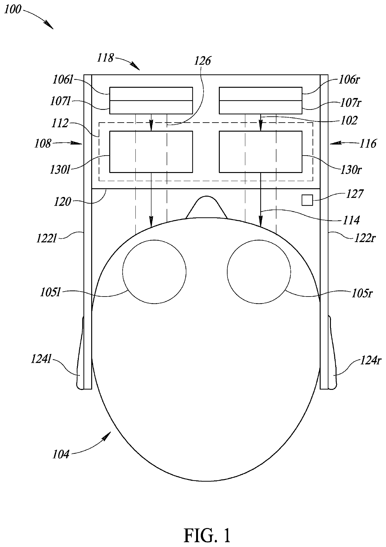
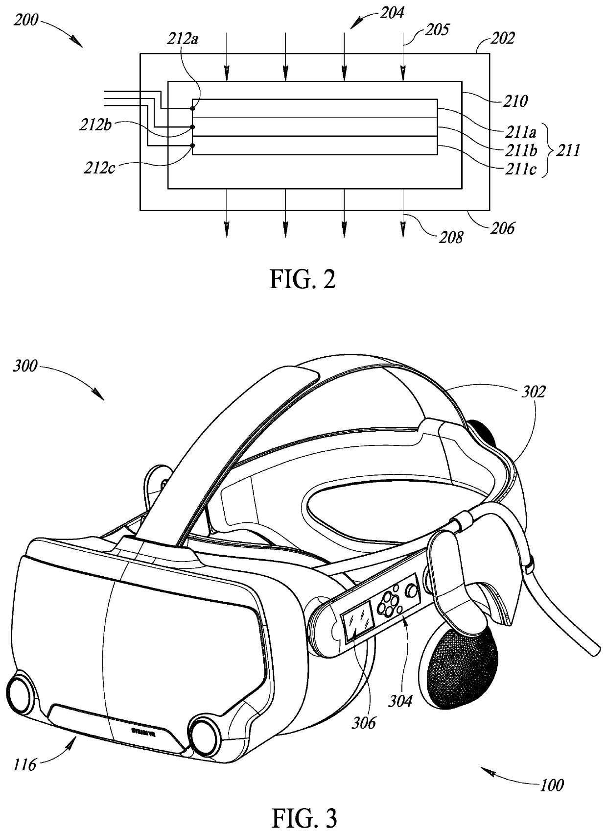
[0004]A head-mounted display may be summarized as including a virtual image display unit and an optical system for modifying virtual image light. The optical system may modify virtual image light to enhance user experience or viewing or improve the angular resolution of the virtual image light. The optical system may perform optical correction to modify a focal length of virtual image light or sharpen the virtual image light. In particular, the optical system may target, modify or operate upon light in a specific portion of the virtual image light that is being viewed or looked at by a user. The portion of the virtual image light may fall within a present field of view of the user. The optical correction may, therefore, be localized to the portion of the virtual image light.

Problems solved by technology

Conventional HMDs do not account for a user's viewing angle or viewing field.

Method used


Image

  • Viewing field-based optical correction using spatially varying polarizers
  • Viewing field-based optical correction using spatially varying polarizers
  • Viewing field-based optical correction using spatially varying polarizers

Examples


Embodiment Construction

[0018]In the following description, certain specific details are set forth in order to provide a thorough understanding of various disclosed implementations. However, one skilled in the relevant art will recognize that implementations may be practiced without one or more of these specific details, or with other methods, components, materials, etc. In other instances, well-known structures associated with computer systems, server computers, and / or communications networks have not been shown or described in detail to avoid unnecessarily obscuring descriptions of the implementations.

[0019]Unless the context requires otherwise, throughout the specification and claims that follow, the word “comprising” is synonymous with “including,” and is inclusive or open-ended (i.e., does not exclude additional, unrecited elements or method acts). References to the term “set” (e.g., “a set of items”), as used herein, unless otherwise noted or contradicted by context, is to be construed as a nonempty ...


PUM


Abstract

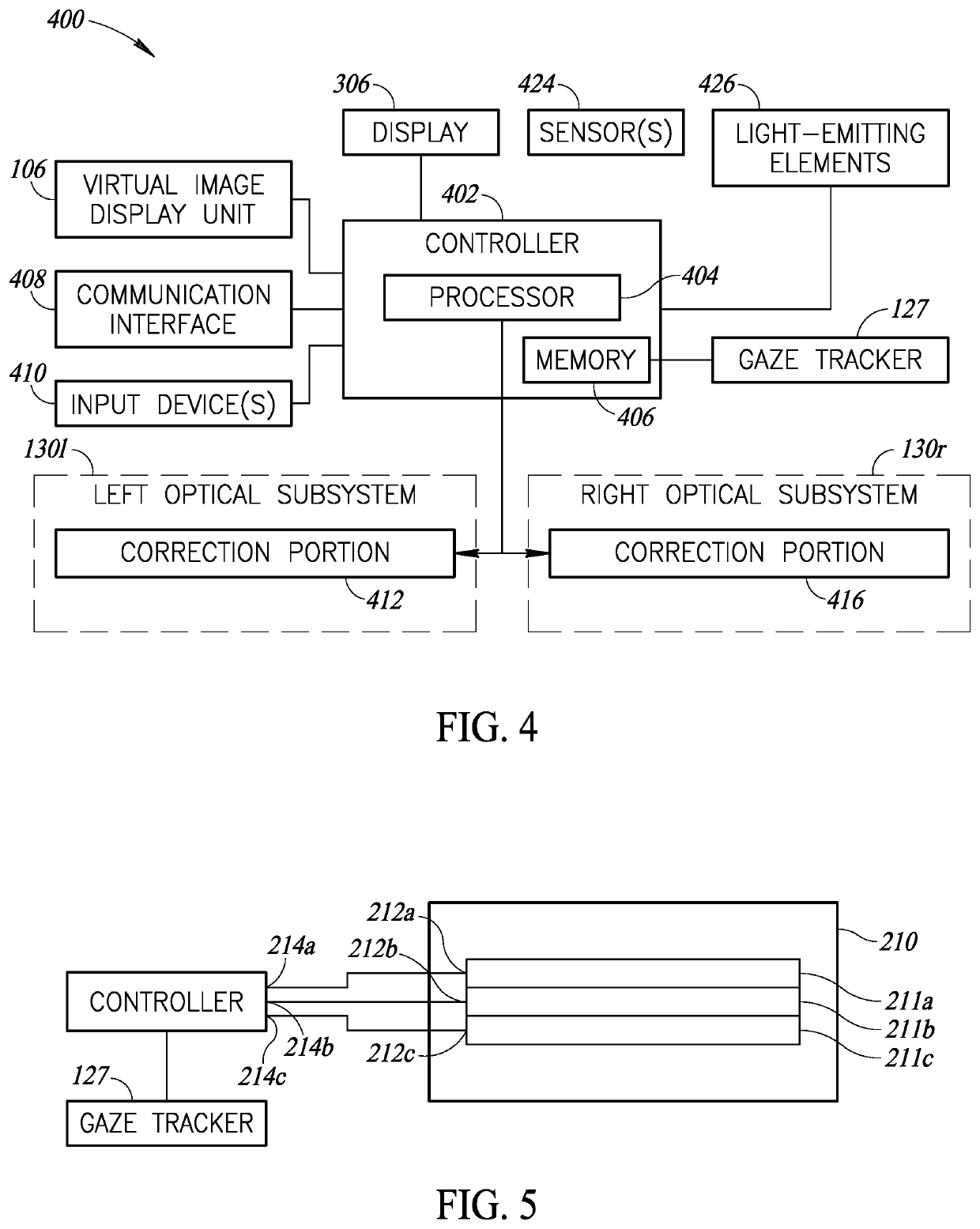
An optical system is provided. The optical system includes a gaze tracker operative to track a gaze of a user and output data representative of the gaze and a correction portion including multiple spatially varying polarizers. A first polarizer of the spatially varying polarizers has a first control input configured to receive a first control signal indicating whether the first polarizer is to be active or inactive. The first polarizer, when active, provides a first optical correction on light passing through at a location corresponding to a first region of a virtual image. The optical system includes a controller configured to receive the data representative of the gaze, determine, based on the gaze, whether to implement the first optical correction on the light and in response to determining to implement the first optical correction on the light, output the first control signal indicating the first polarizer is to be active.

Description

BACKGROUNDTechnical Field[0001]The present disclosure relates to an optical correction system performing viewing-field based optical correction using spatially varying polarizers.Description of the Related Art[0002]Head-mounted display devices (HMDs) are display devices, worn on the head of a user, having one or more display units for presenting visual content to a user. HMDs are becoming increasingly popular to provide virtual reality (VR) or augmented reality (AR) experiences, or to facilitate gaming or presentation of audiovisual media. The display units are typically miniaturized and may include CRT, LCD, Liquid crystal on silicon (LCos), or OLED technologies, for example. Some HMDs are binocular and have the potential to display a different image to each eye. This capability is used to display stereoscopic images to present a more immersive user experience.[0003]Conventional HMDs do not account for a user's viewing angle or viewing field. Conventional HMDs display visual conten...

Claims


Application Information

Patent Timeline
Patent Type & Authority Applications(United States)
IPC IPC(8): G02B27/01G02B27/00G02B5/30
CPCG02B27/0172G02B27/0093G02B2027/014G02B5/3083G02B5/3016G02B5/3025G02B27/4261G02B2027/0147G02B27/286G02B2027/011
Inventor HUDMAN, JOSHUA MARK
Owner VALVE
Why Eureka
Try Eureka