Racket

a racket and racket body technology, applied in the field of rackets, can solve the problems of affecting the rebound performance and the appearance of the racket, the racket is large in mass, and the frame strength is affected, and achieves excellent rebound performan

Pending Publication Date: 2021-08-19
SUMITOMO RUBBER IND LTD
View PDF0 Cites 0 Cited by
  • Summary
  • Abstract
  • Description
  • Claims
  • Application Information

AI Technical Summary

Benefits of technology

[0011]When a ball or the like is hit with the racket according to the present invention, upon impact with the ball or the like, the base deflects toward the center of the face. The deflection is a minute deformation. After the impact, the deformed base becomes restored. By the deformation and restoration, great kinetic energy is transferred to the ball or the like. The racket has excellent rebound performance.

Problems solved by technology

The variation in the depths of the grooves impairs the rebound performance and the appearance of the racket.
However, when the thickness of the grommets is excessively great, the mass of the racket is great.
In this case, however, the presence of the deep grommet grooves would impair the strength of the frame.
Thus, the improvement of the rebound performance by utilizing the shanks have certain limitations.

Method used


Image

  • Racket
  • Racket
  • Racket

Examples


experiment 1

Example 1

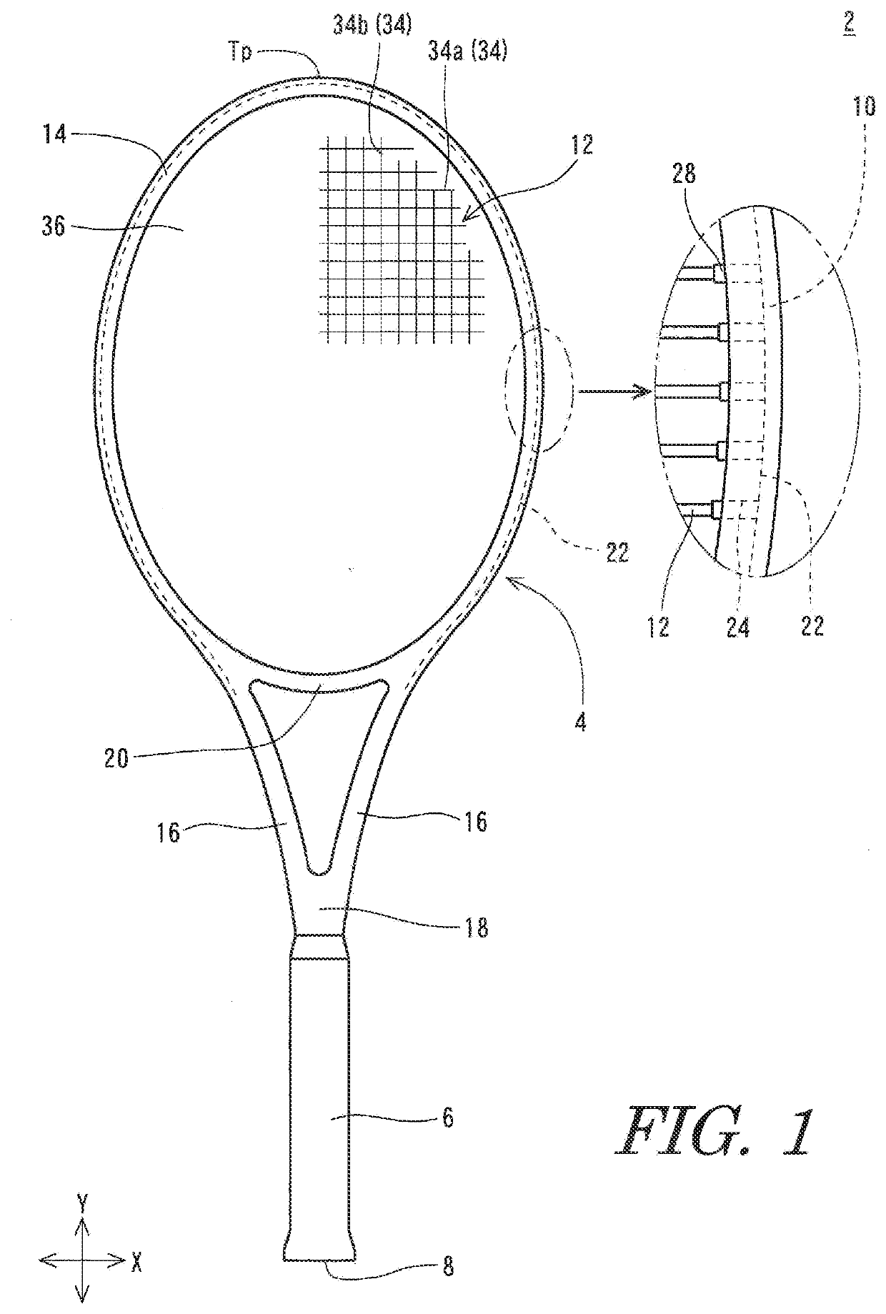
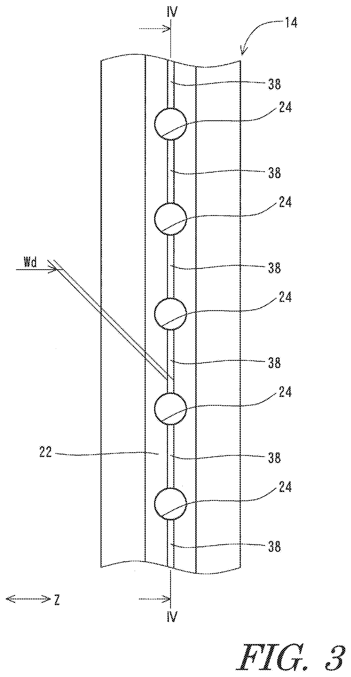
[0067]The prepreg matrix resin was cured in the mold having the ridges, and thereby a frame was produced. By using the frame, the tennis racket shown in FIGS. 1 to 8 was obtained. The racket includes a large number of small grooves. The width Wd of each small groove is 1.0 mm. The depth Dp of each small groove is 0.5 mm.

experiment 2

[0071]For each of the tennis rackets of Example 1 and Comparative Example 1 used in Experiment 1, the rebound coefficient was measured at eight measurement points shown in Table 2 below. In Table 2, x is a distance in the X direction from an origin, and y is a distance in the Y direction from the origin. The origin is the top of the head.

TABLE 2Measurement points of the rebound coefficient.First measurement pointx = 0 cmy = 9 cmSecond measurement pointx = 0 cmy = 12 cmThird measurement pointx = 0 cmy = 15 cmFourth measurement pointx = 0 cmy = 18 cmFifth measurement pointx = 0 cmy = 21 cmSixth measurement pointx = 0 cmy = 24 cmSeventh measurement pointx = 0 cmy = 27 cmEighth measurement pointx = 0 cmy = 30 cm

[0072]FIG. 11 illustrates a graph showing the measurement results. In FIG. 11, the horizontal axis indicates the distance from the top to each measurement point, and the vertical axis indicates the rebound coefficient. It is clear from FIG. 11 that the tennis racket of Example 1 ...

experiment 3

Examples 2 to 4

[0073]Tennis rackets of Examples 2 to 4 were obtained in the same manner as Example 1, except that different molds were used in Examples 1 to 4, respectively. The groove sizes of these tennis rackets are shown in Table 3 below.

Rebound Coefficient

[0074]The rebound coefficient at the center of the face of each tennis racket was measured by using the same method as that of Experiment 1. The measurements results are shown in Table 3 below.

TABLE 3Measurement results of the rebound coefficient.WdDpRebound CoefficientExample 20.5 mm0.5 mm0.355Example 11.0 mm0.5 mm0.361Example 31.5 mm0.5 mm0.365Example 41.0 mm0.2 mm0.360Comp. Ex.  0 mm  0 mm0.346

[0075]It is clear from Table 3 that the tennis racket of each Example has excellent rebound performance.


PUM


Abstract

A tennis racket includes a frame and a grommet. The frame includes a grommet groove, a small groove, and a hole. The small groove is recessed from the grommet groove. The grommet includes a base and a pipe. In a state where the grommet is attached to the frame, the base is accommodated in the grommet groove, and the pipe extends through the hole. The base is not positioned inside the small groove. Therefore, at the back of a back side surface of the base, there is a space derived from the small groove.

Description

CROSS-REFERENCE TO RELATED APPLICATION[0001]This application claims priority to and the benefit of Patent Application No. 2020-023520 filed in JAPAN on Feb. 14, 2020, the entire disclosure of which is incorporated herein by reference.BACKGROUND OF THE INVENTIONField of the Invention[0002]The present invention relates to rackets for use in, for example, tennis.Description of the Related Art[0003]A tennis racket includes a frame and a string. A tennis player hits a ball with the racket. The ball, after being hit, flies toward the opponent's court. A ball that flies at high speed can contribute to the tennis player's win.[0004]Japanese Laid-Open Patent Application Publication No. 2019-107057 discloses a tennis racket having grooves formed in its frame. The racket having the grooves becomes deformed to a great degree upon impact with the ball. Therefore, the racket has excellent rebound performance.[0005]In the old days, the string was directly inserted through holes formed in the frame...

Claims


Application Information

Patent Timeline
Patent Type & Authority Applications(United States)
IPC IPC(8): A63B49/022
CPCA63B49/022A63B2102/02A63B49/02A63B2209/00A63B49/028A63B60/52A63B2049/0201A63B2049/0204
Inventor YAMAMOTO, YOSUKESAKAMOTO, NAOKA
Owner SUMITOMO RUBBER IND LTD
Why Eureka
Try Eureka