Unlock instant, AI-driven research and patent intelligence for your innovation.

Position detection method, position detection device, and display device

a technology of position detection and display device, which is applied in the direction of picture reproducers using projection devices, television systems, instruments, etc., can solve the problem of difficult to determine whether or not the pointing element has contact with the operation surfa

Active Publication Date: 2021-08-19
SEIKO EPSON CORP
View PDF3 Cites 2 Cited by
  • Summary
  • Abstract
  • Description
  • Claims
  • Application Information

AI Technical Summary

Benefits of technology

The present patent is about a position detection method for a pointing element on an operation surface using infrared light. The method involves irradiating the operation surface with infrared light, taking two images with different viewpoints, removing noise components from the images, and extracting an area where the pointing element is likely to be located. The method can be implemented using a learned neural network to determine the pointing position and whether or not the pointing element has contact with the operation surface. The technical effect of the patent is to provide a more accurate and efficient method for position detection in an operation surface using infrared light.

Problems solved by technology

However, it is difficult to determine whether or not the pointing element has contact with the operation surface.

Method used


Image

  • Position detection method, position detection device, and display device
  • Position detection method, position detection device, and display device
  • Position detection method, position detection device, and display device

Examples


Embodiment Construction

[0042]Hereinafter, an embodiment of the present disclosure will be described with reference to the drawings.

A-1. Configuration of Interactive Projection System

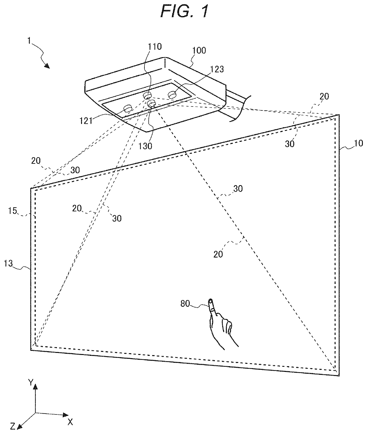
[0043]FIG. 1 is a perspective view of an interactive projection system 1.

[0044]The interactive projection system 1 is provided with a projector 100 and a projection surface 10 on which the projector 100 projects an image. Hereinafter, the description will be presented assuming a normal direction of the projection surface 10 and a front side of the projection surface 10 as a Z-axis direction, a vertically upward direction along the projection surface 10 as a Y-axis direction, and a direction perpendicular to the Z-axis direction and the Y-axis direction as an X-axis direction. The projection surface 10 corresponds to an X-Y plane with Z=0. Further, the projection surface 10 is a display surface on which image light 30 projected by the projector 100 is displayed, and the projector 100 is an example of a display device.

[0045]The ...


PUM


Abstract

The position detection method of detecting a position in an operation surface pointed by a pointing element includes obtaining a first taken image with the first camera configured to take an image with the infrared light, obtaining a second taken image with the second camera configured to take an image with the infrared light, removing a noise component from the first and second taken image, converting the first and second taken image from which the noise component removed into a first and second converted taken image, forming a difference image between the first converted taken image and the second converted taken image, extracting an area in which a disparity amount between the first converted taken image and the second converted taken image is within a predetermined range out of the difference image as a candidate area, detecting a tip position of the pointing element from the candidate area, and determining a pointing position of the pointing element and whether or not the pointing element had contact with the operation surface based on a result of the detecting.

Description

[0001]The present application is based on, and claims priority from JP Application Serial Number 2020-024060, filed Feb. 17, 2020, the disclosure of which is hereby incorporated by reference herein in its entirety.BACKGROUND1. Technical Field[0002]The present disclosure relates to a position detection method, a position detection device, and a display device.2. Related Art[0003]In the past, there has been known a device for detecting a position pointed by a user with a laser pointer or a finger (see, e.g., JP-A-2010-72977 (Document 1)). The device described in Document 1 is a device for projecting an image on a screen, and has a function of detecting a light spot generated on the screen with a laser pointer. This device outputs a position of the light spot using a projected image obtained by detecting an image projected on the screen with a light receiving section, and a background image obtained by detecting a background image projected on the screen with the light receiving sectio...

Claims


Application Information

Patent Timeline
Patent Type & Authority Applications(United States)
IPC IPC(8): H04N9/31G06F3/03H04N5/232G06T7/194G06T7/174
CPCH04N9/3194G06F3/0304G06T7/174G06T7/194H04N5/23229H04N17/002G06F2203/04108G06F3/0421G06V30/32G06V30/1423G06V10/454G06V10/507G06V10/82G06V30/19173H04N23/56H04N23/74H04N23/90H04N23/80
Inventor YANG, JUNFU, GUOYI
Owner SEIKO EPSON CORP