Internal structure of a primary exhaust duct having a separator of which the geometry varies depending on the temperature

Active Publication Date: 2021-08-26
AIRBUS OPERATIONS SAS
View PDF3 Cites 0 Cited by
  • Summary
  • Abstract
  • Description
  • Claims
  • Application Information

AI Technical Summary

Benefits of technology

[0011]The present invention has an object of proposing an internal structure of a primary exhaust duct of a turbomachine which comprises devices for attenuati

Problems solved by technology

A turbomachine of this kind ge

Method used


Image

  • Internal structure of a primary exhaust duct having a separator of which the geometry varies depending on the temperature
  • Internal structure of a primary exhaust duct having a separator of which the geometry varies depending on the temperature
  • Internal structure of a primary exhaust duct having a separator of which the geometry varies depending on the temperature

Examples


Example

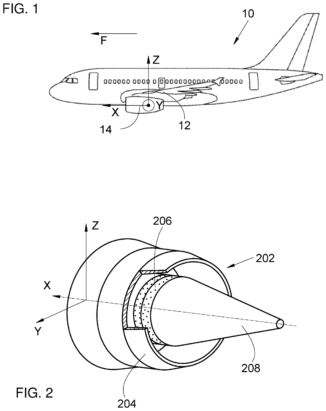
[0029]FIG. 1 shows an aircraft 10 which has a wing 12, beneath which there is attached a nacelle 14 which houses a turbomachine.

[0030]In the following description, and as is conventional, the X axis is the longitudinal axis of the turbomachine, with positive orientation in the direction of forward movement of the aircraft 10, this also being the longitudinal axis of the nacelle 14; the Y axis is the transverse axis which is horizontal when the aircraft 10 is on the ground; the Z axis is the vertical axis or vertical height when the aircraft 10 is on the ground; these three directions X, Y and Z are mutually orthogonal.

[0031]In the following description, terms relating to a position are considered with reference to the direction of movement of the aircraft 10 when the turbomachine is in operation, and indicated by the arrow F.

[0032]FIG. 2 shows the rear part of the turbomachine which forms a primary exhaust duct 202 via which the gases burnt by the turbomachine escape and which is de...


PUM


Abstract

An internal structure of a primary exhaust duct of a turbomachine, which has a primary wall allowing air to pass through orifices and forming an internal surface of the primary exhaust duct, an interior skin arranged inside the primary wall, and at least one separator of which a first edge region is attached to the interior skin and which has two geometries. A change from the first geometry to the second takes place when the temperature of the separator exceeds a first temperature, and the change from the second to the first takes place when the temperature of the separator drops below a second temperature. The coefficient of expansion of the separator is greater than that of the interior skin. The variation in the geometry of the separators depending on the temperature of the engine eases assembly at ambient temperature due to the compression of the separators.

Description

CROSS-REFERENCES TO RELATED APPLICATIONS[0001]This application claims the benefit of the French patent application No. 2001801 filed on Feb. 24, 2020, the entire disclosures of which are incorporated herein by way of reference.FIELD OF THE INVENTION[0002]The present invention relates to an internal structure of a primary exhaust duct of a turbomachine which has at least one separator of which the geometry varies depending on the temperature, to a turbomachine having such an internal structure, and to an aircraft having at least one such turbomachine.BACKGROUND OF THE INVENTION[0003]A turbomachine conventionally has, from upstream to downstream, an air inlet through which the air enters the turbomachine, an engine which combusts the air and fuel, and an exhaust duct through which the burnt gases are evacuated.[0004]A turbomachine of this kind generates noise during operation.[0005]In order to attenuate some of this noise, the turbomachine is surrounded with a nacelle having noise att...

Claims


Application Information

Patent Timeline
IPC IPC(8): F01D25/30F01D9/06F01D25/28F02K1/34
CPCF01D25/30F01D9/06F01D25/28F05D2260/963F05D2220/323F05D2250/90F05D2260/31B64D33/06F02K1/827F02K1/04F05D2300/505F05D2300/50212F05D2230/60Y02T50/60F02K1/085
Inventor ANDRE, SANDRINETROCELLIER, VINCENTFERREIRA, JULIENKILKENNY, MICHAEL
Owner AIRBUS OPERATIONS SAS
Why Eureka
Try Eureka