Stand and lighting device

a technology of lighting device and stand, which is applied in the direction of fixed installation, lighting and heating apparatus, lighting support devices, etc., can solve the problems of relatively unreliable keeping the cover open position, relative difficulty and cost of manufacture, and achieve the effect of avoiding the risk of permanent deformation of the stand, easy and fast operation

Active Publication Date: 2021-08-26
SIGNIFY HLDG BV
View PDF0 Cites 0 Cited by
  • Summary
  • Abstract
  • Description
  • Claims
  • Application Information

AI Technical Summary

Benefits of technology

[0019]The stand could have the feature that each seat is formed as a slot having an open side and comprising both a respective seat and hole at the open side of the slot, and wherein the open side of the slot is reversibly closeable, for example by a screw, a rotatable lid or a hook as closing means. This enables a simple exchange of different stays (to be) accommodated in the supports, without the risk of permanent deformation of the stand as could more likely be the case when the stay has to be removed from the stand by axially forcing the axial portions out of the holes.
[0020]The stand could have the feature that the connect portions extend at mutually different angle β from plane P. When the difference in angle β, i.e. Δβ, between the two connect portions is in the range of 3 to 10 degrees, essentially the same effect is obtained as when the supports are mutually slightly tilted over the rotation axis, for example by said 3 to 10 degrees. This results in the connect portions to extend in the seats at slightly different angles and counteract small movements in orientation of the stay in the first and / or second orientation / position as by this slight tilt the play of the stay with the connect portions in the seats, i.e. when the stay is in the first or second orientation / position, is essentially compensated. Yet, if the difference in angle β between the two connect portions is significantly larger than 10 degrees, for example between 45 and 135 degrees. This has the advantage that a stand is obtained with a stay having three or four positions / orientations in which one connect portion is seated in a seat of the stay, i.e. there are three or four positions in which the stay is blocked against rotation and hence cannot rotate about the rotation axis but is kept fixed in its actual orientation.
[0021]The invention further relates to a luminaire / lighting device comprising a stand according to the invention. Lighting device could for example be a cover of a luminaire housing. In particular such a stand finds application in luminaires / lighting devices which need servicing in places subject to high altitude or traffic volume. Said servicing can be done easily and quickly when the person has two hands available and yet is not exposed to a significant risk of the cover falling on his hands when working at the light engine accommodated in the housing of the luminaire.
[0022]Luminaire / Lighting device could have the feature that the luminaire comprises a housing typically for accommodating a light engine and a housing part, for example a cover, which, via die casting is integrally formed with the supports. A cheap way to manufacture housing parts or covers for luminaires is via die casting. It is convenient to have the supports integrally casted with said housing part / cover in a single manufacturing step. This saves separate manufacture steps of the supports and saves separate mounting steps of the supports on the housing part / cover during the manufacture of the luminaire. Thixomolding can also be used as a manufacturing method as an alternative for die-casting (and plastic injection molding).

Problems solved by technology

The known stand has as disadvantages that it is relatively difficult and expensive to manufacture and that it is relatively unreliable in keeping the cover in open position.

Method used


Image

  • Stand and lighting device
  • Stand and lighting device
  • Stand and lighting device

Examples


Embodiment Construction

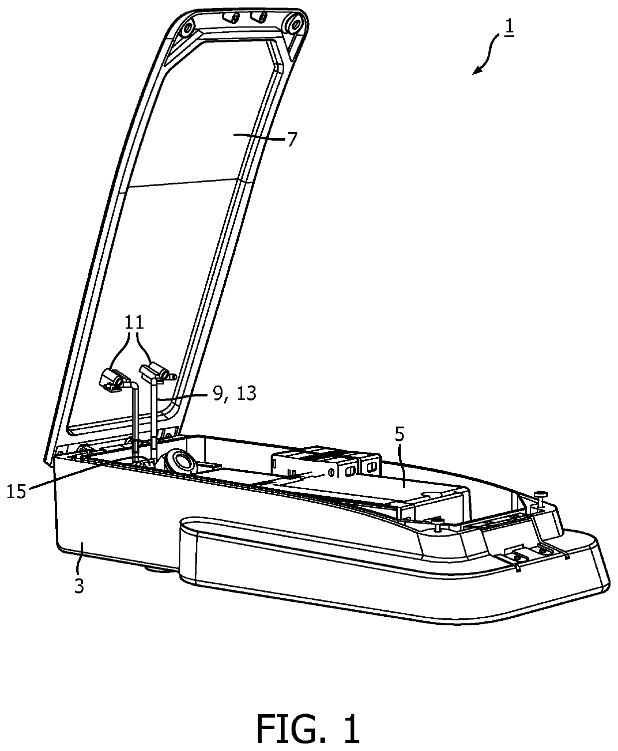
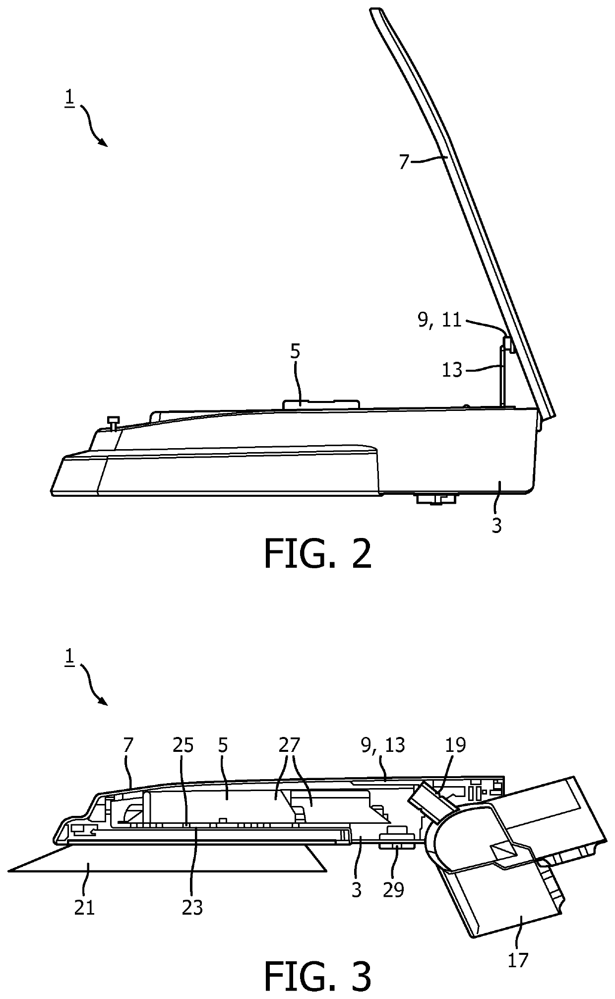
y shows a perspective view and a side view of a luminaire 1 according to the invention in an opened position. The luminaire comprises a housing 3 accommodating a light engine 5 and a cover 7 for said housing hingingly connected thereto. The luminaire further comprises a stand 9 by which the cover is kept in an open position with respect to the housing. The stand comprises two supports 11 which are (partly) integrally formed with the cover and in which a stay 13 is partly accommodated. The stay is in a first position / orientation and extends from the supports to a stopper 15 in the housing on which it rests due to the weight of the cover. The stay rests with outwardly directed pressing force, i.e. the transversal portion are urged away from each other, against the supports. Because of the fixed orientation of the stay in the supports, since the stay in its current position in the supports is blocked from rotation, the cover cannot fall down into the closed position thus rendering a sa...


PUM


Abstract

A stand for a lidded box such as a luminaire and a lighting device comprising said stand. Said stand comprising a rotatable resilient stay and comprising a bridge portion connecting two transversal portions. Each transversal portion having a respective axial portion extending over a rotation axis. Said stand further comprising two facing supports comprising a seat. The seat being elongated in a length direction transverse to the rotation axis, said length direction and rotation axis extend in a plane P. Each axial portion being accommodated in a respective axially extending hole, provided in a respective support, the respective holes and seat being positioned aligned on the rotation axis. The transversal portions having a connect portion connecting the transversal portion with its axial portion, whereby in a seated position of the stay the connect portion extends through the seat in plane P and at an angle α with the length direction, with α in a range of 25° to 75°.

Description

FIELD OF THE INVENTION[0001]The invention relates to a stand and to a lighting device comprising said stand.BACKGROUND OF THE INVENTION[0002]In order that maintenance work on lighting equipment such as replacement and cleaning of street lamps, tunnels luminaires, luminaires installed in places subject to high altitude or traffic volume, can be done easily and quickly, the lighting equipment usually is provided with a latch or stand. A luminaire comprising a latch is, for example, disclosed in CN104406073A. The known luminaire comprises upper cover hingingly connected via a rotation body to a luminaire body. The rotation body comprises a rotatable stay wherein one end is fixed at the rotation body and wherein the other end of the rotatable stay is pressed by the weight of the cover against a stopper provided on the cover itself to enable the cover to stay in an open position during servicing of the luminaire. The known stand has as disadvantages that it is relatively difficult and ex...

Claims


Application Information

Patent Timeline
Patent Type & Authority Applications(United States)
IPC IPC(8): F21V17/10F21V21/06E05C17/04F21V15/01
CPCF21V17/107F21V15/01E05C17/04F21V21/06F21S8/086F21W2131/103F21S8/085F21S8/088F21V15/012
Inventor VERHOEVEN, MARK JOHANNES ANTONIUS
Owner SIGNIFY HLDG BV
Why Eureka
Try Eureka