Inductor component

Pending Publication Date: 2021-09-09
MURATA MFG CO LTD
View PDF0 Cites 0 Cited by
  • Summary
  • Abstract
  • Description
  • Claims
  • Application Information

AI Technical Summary

Benefits of technology

The patent text describes a configuration where a protrusion is added to an inductor wire. This protrusion increases the contact area between the inductor wire and the element body, which prevents displacement of the wire from its designed position. Additionally, the area ratio of the protrusion to the wire main body is less than or equal to 7.2%, which prevents the protrusion from becoming too large and reducing the inductance of the inductor component. Overall, this configuration prevents or reduces displacement of the inductor wire and maintains its performance.

Problems solved by technology

Such a partial positional displacement of the wire main body can be a cause of inductance error of the inductor component, and is therefore not preferable.

Method used


Image

  • Inductor component
  • Inductor component
  • Inductor component

Examples


Embodiment Construction

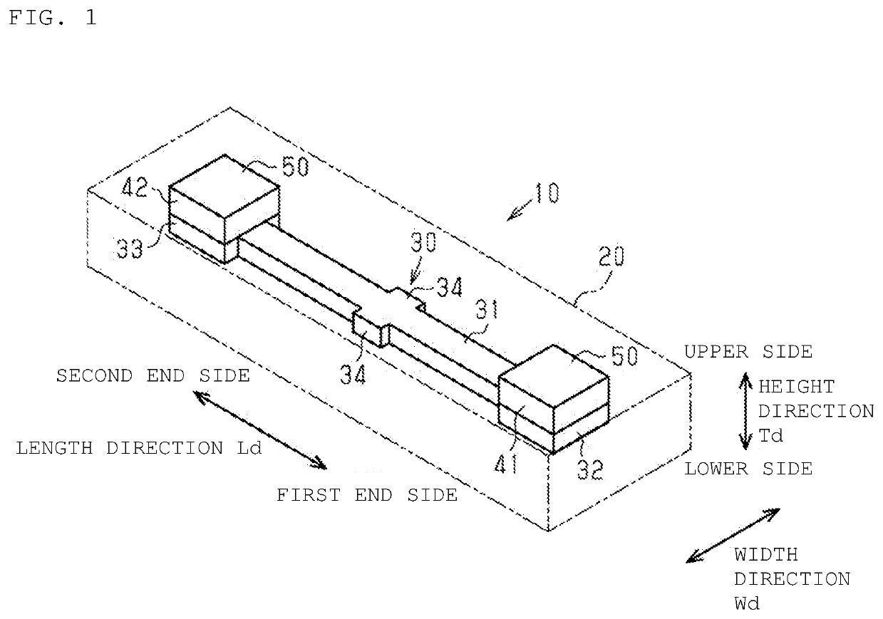
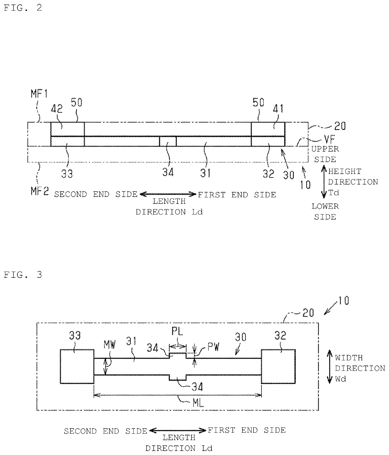
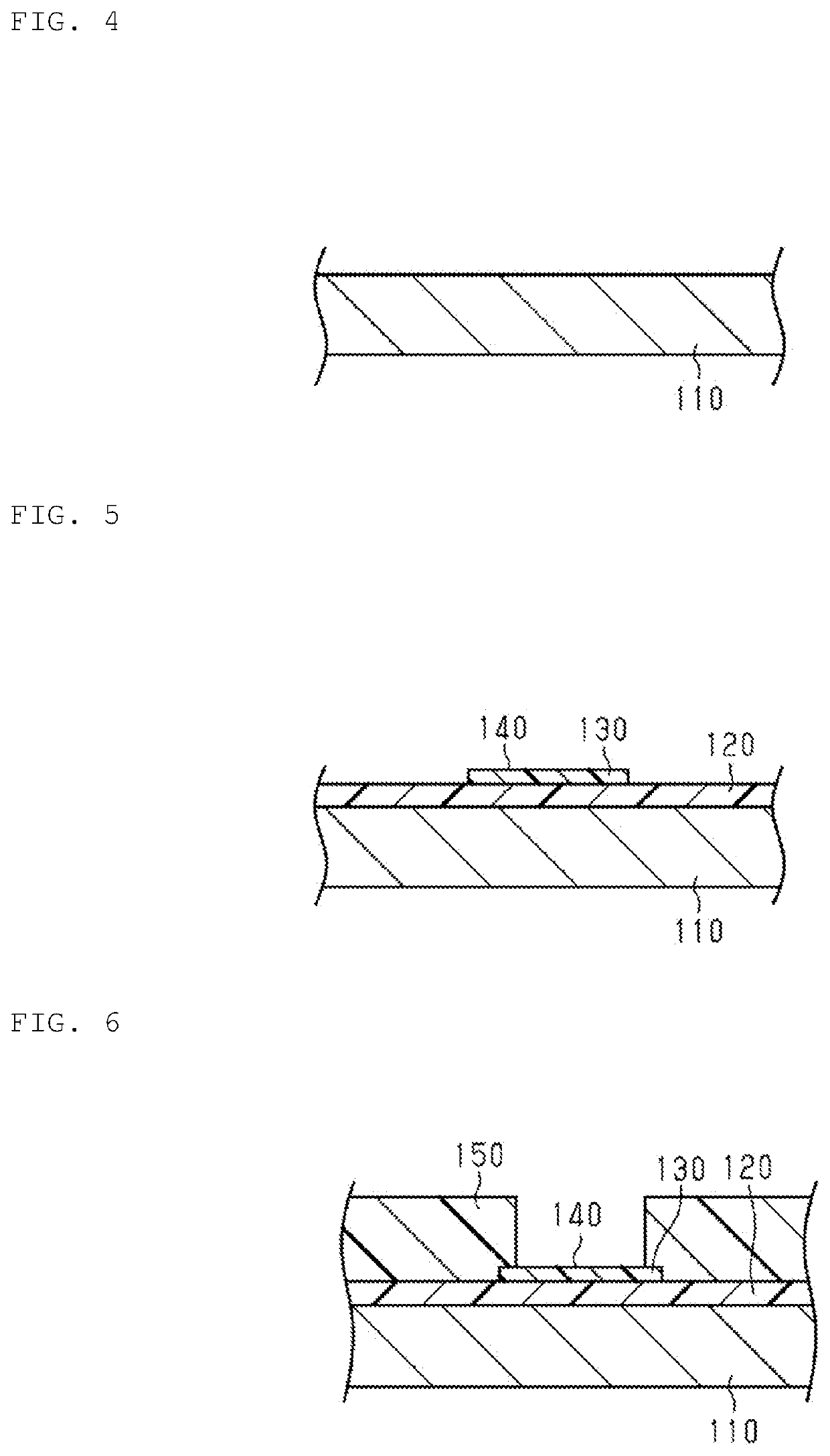
[0025]In the following, an embodiment of an inductor component will be described. Note that the drawings show enlarged views of components in some cases for easy understanding. Dimensional ratios of components are sometimes different from actual dimensional ratios or dimensional ratios in other drawings.

[0026]As shown in FIG. 1, an inductor component 10 includes an element body 20 configured of a magnetic material. The element body 20 has an outer appearance of a flat quadrangular prism. A material of the element body 20 is resin containing a metal magnetic powder such as iron and works as a magnetic material having magnetism as a whole. Note that, in the following description, a center axial line-direction of the element body 20 is assumed as a length direction Ld. In addition, a height direction Td and a width direction Wd that are perpendicular to the length direction Ld are defined as follows. Specifically, the height direction Td is the direction that is one of directions perpe...


PUM


Abstract

In an inductor component, an inductor wire is in an element body and extends on a virtual flat plane passing inside the element body. A wire main body of the inductor wire has an oblong rectangular shape elongated in a length direction in the top view, and thus, a wire width perpendicular to the extending direction is constant. From each edge of the wire main body in a width direction, protrusions having an oblong rectangular shape in the top view protrude and extend, from a center of the wire main body in the extending direction of the wire main body, in a direction perpendicular to the extending direction, on both sides in the width direction of the wire main body, with the extending direction sandwiched between the protrusions. An area ratio of a protrusion area of the protrusions to an area of the wire main body is within 7.2%.

Description

CROSS-REFERENCE TO RELATED APPLICATION[0001]This application claims benefit of priority to Japanese Patent Application No. 2020-037788, filed Mar. 5, 2020, the entire content of which is incorporated herein by reference.BACKGROUNDTechnical Field[0002]The present disclosure relates to an inductor component.Background Art[0003]In the inductor component described in Japanese Patent Application Laid-Open No. 2001-196226, an inductor wire is disposed to be sandwiched between a pair of flat plate-shaped magnetic members. The inductor wire includes a wire main body extending in a circular arc-shape. Three terminal parts extend from the wire main body.SUMMARY[0004]With regard to an inductor component as described in Japanese Patent Application Laid-Open No. 2001-196226, a part of a wire main body of an inductor wire is sometimes displaced from a designed position, so that the wire main body is disposed to be tortuous or inclined with respect to a designed extending direction. Such a partial...

Claims


Application Information

Patent Timeline
IPC IPC(8): H01F27/28H01F27/29H01F27/255H01F41/02
CPCH01F27/2828H01F41/0246H01F27/255H01F27/29H01F17/0013H01F17/04H01F27/2804H01F27/292H01F41/041H01F2017/002H01F2017/048H01F2017/0093H01F2027/2809H01F17/0006
Inventor MIYAKE, ISAMUYOSHIOKA, YOSHIMASA
Owner MURATA MFG CO LTD
Why Eureka
Try Eureka