
Eureka
For R&D, Eureka makes reading and utilizing patents & technical documents easy.
Eureka AIR
Designed for self-driven R&D workflows. Generate viable solutions, solve complex R&D challenges, empower your innovation with AI.

Eureka Materials
Designed for material experts only. Revolutionize your material R&D, from search, analyze, to developing new materials.

TechResearch
Generate reliable direction feasibility study reports for your R&D in just a few steps.

TechSeek
Discover and master advanced knowledge NOW. Basics, ideas, possibilities, all at once.

TechMind
As an expert in R&D Theories, TechMind can generates customized viable solutions instantly.

TechRisk
Analyze your overall solution with one click, know your potential R&D risks in advance.

TechMonitor
Get weekly tech updates, stay abreast of the latest tech innovations and key insights.
Pneumatic Tire
- Summary
- Abstract
- Description
- Claims
- Application Information
AI Technical Summary
Benefits of technology
Problems solved by technology
Method used
Image

Examples
example
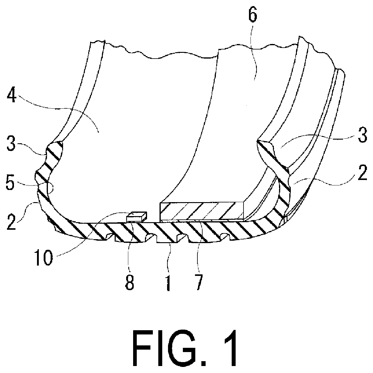
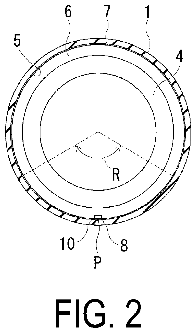
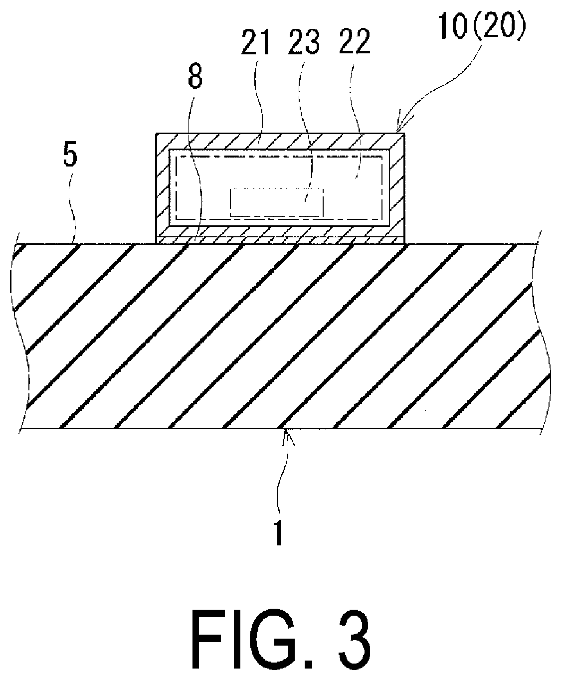
[0053]At a tire size of 275 / 40R21, at least one sound absorbing member having a band-like shape was bonded to an inner surface of a tread portion along a tire circumferential direction, and a correction body for correcting weight unbalance was fixed to a tire inner surface in a range corresponding to a light point in an entire tire including the sound absorbing member. Tires of Examples 1 to 8 in which the numbers of sound absorbing members, positions of the correction bodies on the tire circumferences, and positions of the correction bodies in tire width directions were differentiated as shown in Table 1 were fabricated.
[0054]For comparison, a tire of Comparative Example 1 to which one sound absorbing member was attached to an inner surface of a tread portion and having a structure identical to that of Example 1 except that a correction body was not provided was prepared. Additionally, a tire of Comparative Example 2 to which two sound absorbing members were attached to an inner su...
PUM
 Abstract
Description
Claims
Application Information
 - R&D Engineer
- R&D Manager
- IP Professional
- Industry Leading Data Capabilities
- Powerful AI technology
- Patent DNA Extraction
Browse by: Latest US Patents, China's latest patents, Technical Efficacy Thesaurus, Application Domain, Technology Topic, Popular Technical Reports.
© 2024 PatSnap. All rights reserved.Legal|Privacy policy|Modern Slavery Act Transparency Statement|Sitemap|About US| Contact US: help@patsnap.com