Inner bearing split axle assembly

a technology of axle assembly and split axle, which is applied in the direction of mechanical measuring arrangement, instruments, and ways, can solve the problems of total significant damage to the measurement system of the gauge restraint, and the derailment of the railcar, so as to reduce the balancing moment, improve the tracking of the rails, and reduce the size, weight and cost

Active Publication Date: 2007-08-14
ENSCO INC
View PDF25 Cites 14 Cited by
  • Summary
  • Abstract
  • Description
  • Claims
  • Application Information

AI Technical Summary

Benefits of technology

[0014]A further advantage of the present invention is in providing a novel and improved inner bearing split axle assembly that significantly reduces the balancing moment required so that the associated load bearing components may be reduced in size, weight, and cost.
[0015]Still another advantage of the present invention is in providing a split axle assembly that improves tracking of the rails and facilitates maintaining of consistent lateral force to provide accurate gage measurements and measurement data.
[0016]Yet another advantage of the present invention is in providing a split axle assembly that minimizes binding to facilitate axial movement of wheels.
[0017]These and other advantages are attained by a split axle assembly for obtaining gage measurements of a track in accordance with the present invention comprising a first wheel and a second wheel sized to roll along the track, the first wheel being laterally spaced from the second wheel, a first split axle secured to the first wheel so that the first split axle rotates with the first wheel, a second split axle secured to the second wheel so that the second split axle rotates with the second wheel, a first bearing for rotatably receiving the first split axle, and a second bearing for rotatably receiving the second split axle, where the first bearing and the second bearing are positioned inboard between the first wheel and the second wheel.
[0018]In accordance with one embodiment, the split axle assembly also includes brackets adapted to secure the split axle assembly to a truck or railcar body to allow lowering of the split axle assembly to an operative state, and to retract the split axle assembly to an inactive state. In this regard, one or more cylinders may be provided which is pivotally attached to the brackets that is operable to lower or retract the split axle assembly. The cylinders may be hydraulic cylinders and / or pneumatic cylinders.
[0019]In accordance with one implementation, the split axle assembly may be provided with a sliding barrel device adapted to allow the first wheel and the second wheel to axially move relative to one another. In this regard, the sliding barrel device includes an outer barrel, and at least one inner barrel axially movable in the outer barrel. Preferably, a first inner barrel and a second inner barrel is provided, the first inner barrel being connected to the first split axle and the second inner barrel being connected to the second split axle. In addition, the split axle assembly may further be provided with one or more cylinders for axially moving the first inner barrel and the second inner barrel relative to each other. In this regard, the cylinders may be hydraulic cylinders and / or pneumatic cylinders.

Problems solved by technology

However, if the railroad gage restraint measurement system is mounted on the truck as part of the running gear, the measurement system is significantly damaged if the axle derails.
In addition, such a measurement system can lead to a total derailment of the railcar to which the railroad gage restrain measurement system is attached.
This procedure can be automated, but not without increased complexity and cost.
Furthermore, if active controls are not used for lateral positioning, frictional forces and mass effects can seriously impact the applied forces.
Predicting these effects is nearly impossible until the measurement system is operating under normal loading conditions on the track.
This results in a significant decrease in data quality due to the poor axle tracking, i.e. following rails of the track, and large variations in lateral force.
Another disadvantage in mounting the measurement system to the railcar body is the resulting effect of unloading the vehicle's suspension.
Lastly, the railcar's ride quality may be degraded due to the lack of a suspension between the loaded axle and the car body.
A major disadvantage of the conventional split axle designs is that the bending moment that is transferred across the sliding barrel device to the opposing wheel on the railroad track is generally very high.
The sliding surfaces of the sliding barrel device which allows it to function in a telescoping manner has a tendency to bind, i.e. become temporarily stuck.
Such binding results in random locking of the telescoping action of the split axle assembly so that the split axle does not accurately follow the actual rails of the track.
Binding of the split axle results in excessive variation in the lateral forces which result in poor quality measurement data being obtained.
Further, such binding can damage the track with excessive forces when the gage of the track narrows and the split axle assembly binds during axial movement.
However, since the hydraulic cylinders are applying opposing forces, a large amount of stress is generated in the push-plates 108 and the sliding barrel thereby requiring a significant amount of material to resist deflection.
The amount of material required to resist deflection adds significant cost and weight to the components of the split axle assembly making the axle weigh approximately 6,250 lbs.
In use, however, the shafts of Norby et al. have also been found to bind within the housing thereby causing poor lateral tracking of the rails of the tracks, and also causing significant variations in the exerted lateral force which results in inaccurate gage measurements and measurement data.
Therefore, in view of the above, there exists an unfulfilled need for a split axle assembly for a gage restraint measurement system that avoids the disadvantages of the prior art.
In particular, there still exists an unfulfilled need for a split axle assembly that significantly reduces the balancing moment required so that the associated load bearing components may be reduced in size, weight, and correspondingly, cost.
In addition, there still exists an unfulfilled need for a split axle assembly that improves lateral tracking of the rails of the track and facilitates maintaining of consistent lateral force to provide accurate gage measurements and measurement data.

Method used


Image

  • Inner bearing split axle assembly
  • Inner bearing split axle assembly
  • Inner bearing split axle assembly

Examples


Embodiment Construction

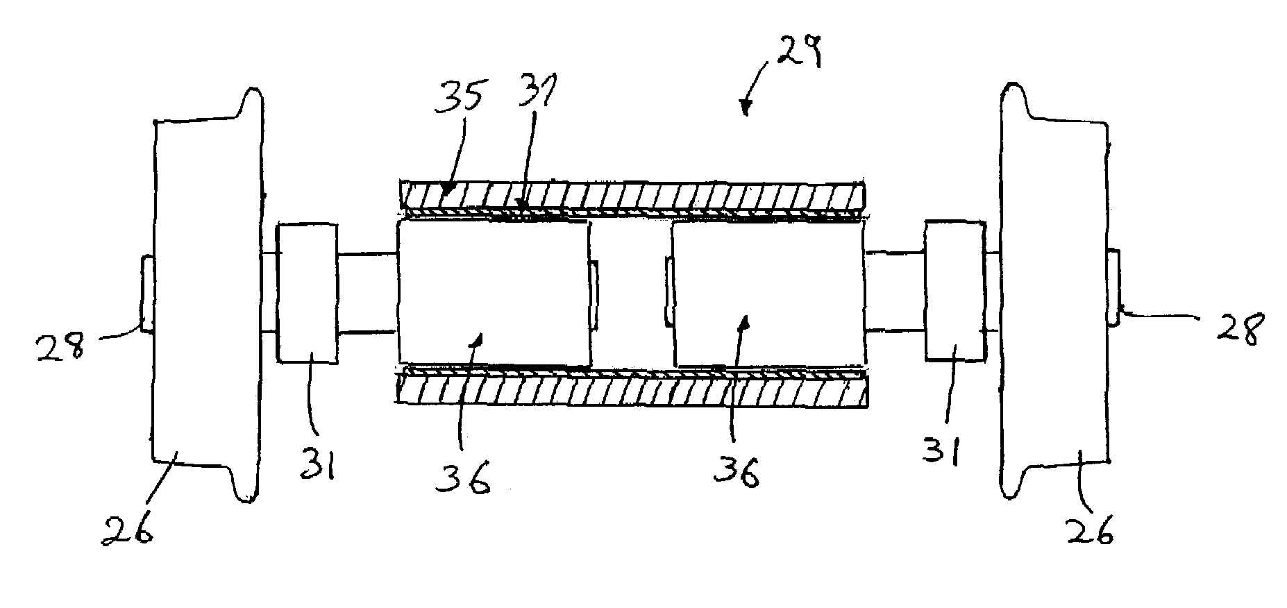
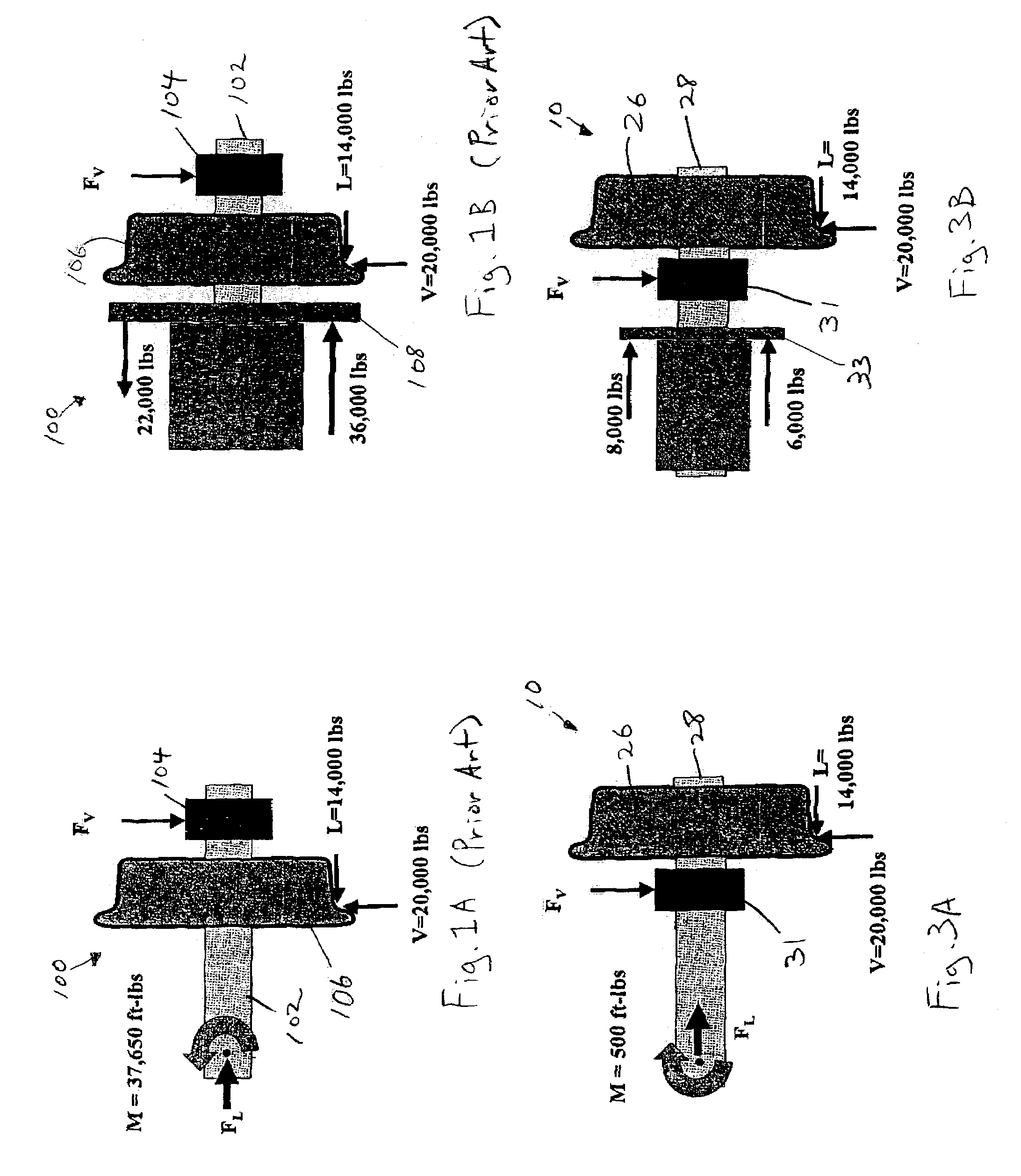
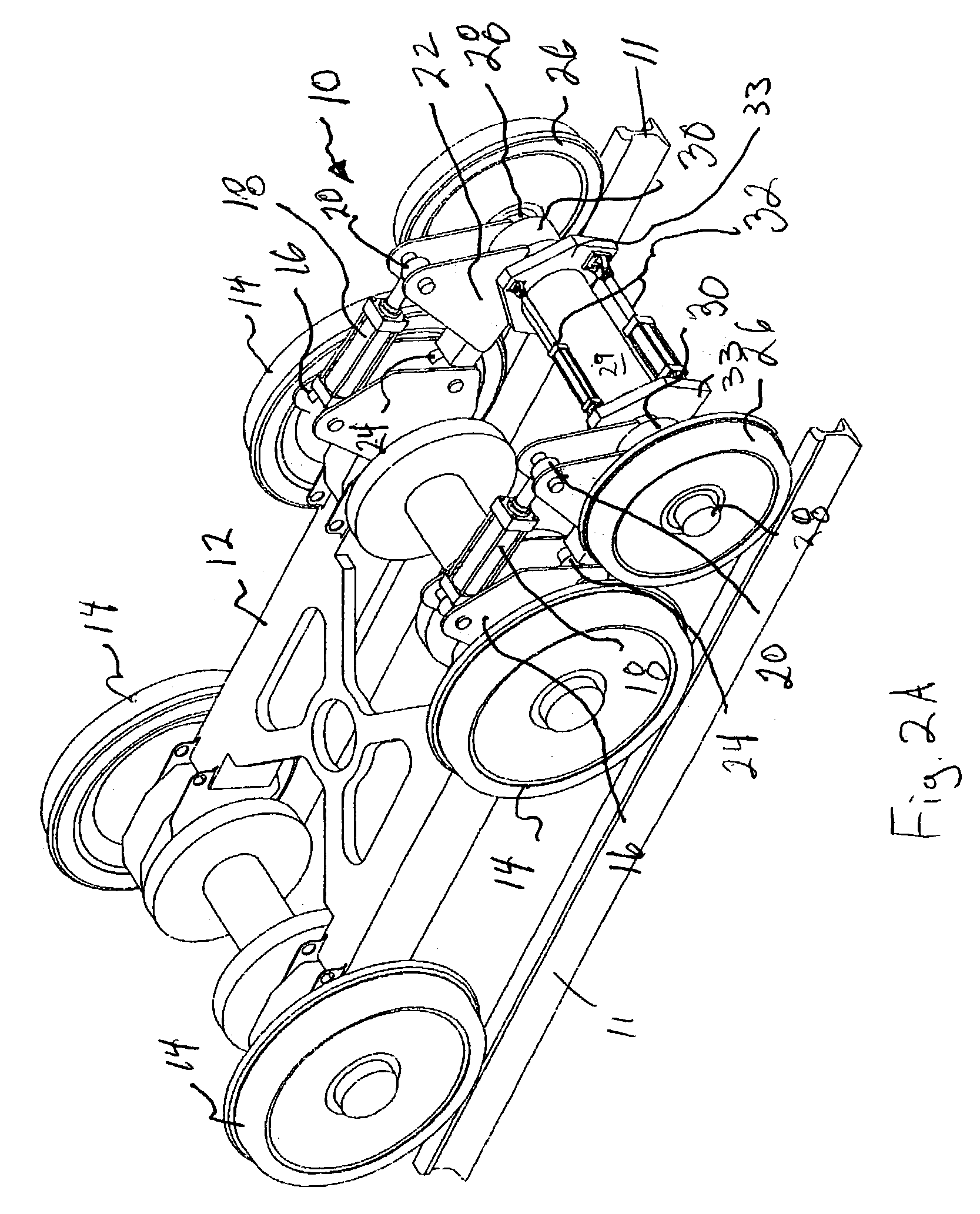
[0034]FIG. 2A shows a split axle assembly 10 for use in a gage measurement system in accordance with one embodiment of the present invention. As will be explained below, the split axle assembly 10 significantly reduces the balancing moment required so that the associated load bearing components may be reduced in size, in weight, and, correspondingly, in cost. In particular, to reduce the balancing moment, as well as the size and weight of the gage measurement system, the split axle assembly 10 of the present invention as shown in FIG. 2A is provided with inner bearings as described in further detail below which are positioned inboard of the wheels of the split axle assembly 10.

[0035]The inner bearing split axle assembly 10 shown in FIG. 2A is illustrated as being mounted to a truck 12 of a railcar (not shown) having four track engaging wheels 14 that roll along the track 11. Of course, it should be understood that the term “railcar” as used herein broadly refers to any vehicle desig...


PUM


Abstract

A split axle assembly for obtaining gage measurements of a track including a first wheel with a first split axle, a second wheel with a second split axle, a first bearing for rotatably receiving the first split axle, and a second bearing for rotatably receiving the second split axle, the first bearing and the second bearing being positioned inboard between the first wheel and the second wheel. In one embodiment, a sliding barrel device is provided. In another embodiment, the first bearing is received in a first bearing body and the second bearing is received in a second bearing body so that they are axially movable relative to one another. At least one linear guide is provided to allow axial movement of the first bearing body and the second bearing body relative to one another.

Description

BACKGROUND OF THE INVENTION[0001]This application claims priority to U.S. Provisional Application No. 60 / 364,604, filed Mar. 18, 2002.FIELD OF THE INVENTION[0002]The present invention relates to an axle assembly for rail vehicles such as railcars, subway cars trains, trolleys and the like. In particular, the present invention relates to such an axle assembly that includes a split axle assembly which allows the wheels to move axially inward and outwardly with reduced binding.Description of Related Art[0003]To ensure safe operation of trains, railcars, subway cars, trolleys and the like, devices have been used to measure gage restraint such as track stiffness and / or tie conditions. Examples of such devices are shown in U.S. Pat. No. 3,643,503 to Plasser et al., U.S. Pat. No. 3,816,927 to Theurer et al., and U.S. Pat. No. 3,869,907 to Plasser, deceased et al. In addition, devices have been designed to apply predetermined lateral force on the track, and to measure the lateral displaceme...

Claims


Application Information

Patent Timeline
Patent Type & Authority Patents(United States)
IPC IPC(8): E01B35/02B61K9/08E01B35/04
CPCB61K9/08E01B35/04
Inventor CARR, GARY A.STUART, CAMERON D.BLOOM, JEFFREY A.
Owner ENSCO INC
Why Eureka
Try Eureka