Flow control device for tundish of slab continuous caster and deslagging method thereof

A slab continuous casting machine and tundish technology, which is applied to casting equipment, casting melt containers, metal processing equipment, etc., can solve the problems of resistance to molten steel erosion, low service life, and poor scouring performance of impact pads

Active Publication Date: 2012-10-24
LAIWU STEEL YINSHAN SECTION CO LTD
View PDF8 Cites 17 Cited by
  • Summary
  • Abstract
  • Description
  • Claims
  • Application Information

AI Technical Summary

Problems solved by technology

At present, after the flow control device is installed in the tundish of the slab continuous casting machine, there are new technical problems: (1) The slag retaining weir is installed, and the steel slag floating in the tundish cannot be discharged regularly through the tundish overflow port. It can shorten the continuous pouring time of the tundish, resulting in an increase in the production cost of continuous casting; (2) Set up a slag dam to block part of the molten steel from flowing out after the tundish stops pouring, thereby increasing the excess of the tundish and reducing the slab (3) The flow control device is not resistant to erosion and erosion, and its service life is low, which has become a bottleneck problem that restricts the improvement of the life of the slab continuous casting tundish, resulting in an increase in continuous casting production costs
Defects of this invention: 1) The upper edge of the slag retaining weir is flush with the edge of the tundish, and the steel slag floating in the tundish cannot be discharged regularly through the tundish overflow port, and the continuous pouring time of the tundish can only be shortened , generally less than 8 hours; 2) There is no through hole on the slag retaining dam. After the tundish stops pouring, part of the molten steel is blocked from flowing out, thereby increasing the tundish injection surplus; the slag retaining dam adopts the existing production technology, and its resistance to molten steel Erosion and scouring performance are poor, and the service life is generally less than 8 hours; 3) The bottom of the tundish where the molten steel is injected into the tundish adopts a traditional impact pad without a turbulence controller, which is beneficial to prolonging the residence time of molten steel in the tundish and promoting The effect of floating and removing inclusions is greatly weakened, and the impact pad resists molten steel erosion and has poor scouring performance, and its service life is generally less than 10 hours

Method used


Image

  • Flow control device for tundish of slab continuous caster and deslagging method thereof
  • Flow control device for tundish of slab continuous caster and deslagging method thereof
  • Flow control device for tundish of slab continuous caster and deslagging method thereof

Examples


Embodiment 1

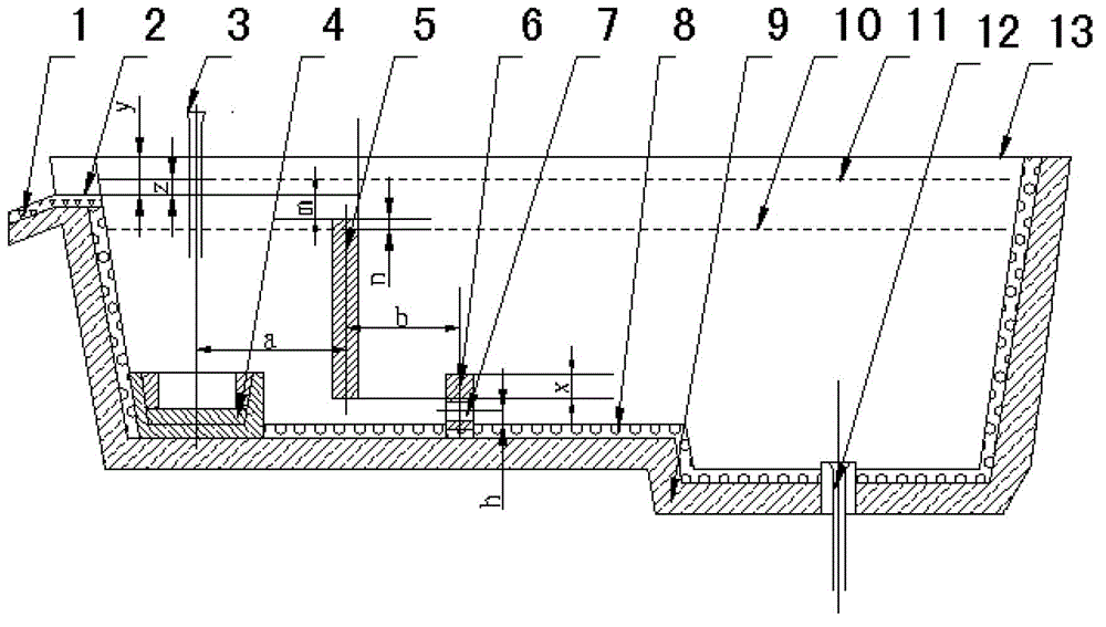
[0052] Such as figure 1 , figure 2 , image 3 , Figure 4 As shown, a tundish flow control device for a slab continuous casting machine includes a turbulent flow controller 4, a slag retaining weir 5, and a slag retaining dam 6, and the turbulent flow controller 4 is installed on the working lining 8 of the tundish injection impact area. On the inner side, its center line coincides with the center line of the long nozzle 3 of the ladle, the slag retaining weir 5 is fixed on the working lining 8 of the tundish wall, and the slag retaining dam 6 is fixed on the working lining 8 of the tundish bottom. The distance n between the upper edge of the slag weir 5 and the maximum liquid steel level 10 of the tundish normally poured is 50 mm, and the distance m between the upper edge of the slag weir 5 and the working surface of the smear material 1 at the overflow port of the tundish is 50 mm . The staggered height x of the slag retaining weir 5 and the slag retaining dam 6 is 100 ...

Embodiment 2

[0075] Others are the same as embodiment 1, the difference is:

[0076] The distance n of the upper edge of the slag retaining weir 5 higher than the maximum liquid steel level 10 of the tundish normally poured is 20 mm, and the distance m of the upper edge of the slag retaining weir 5 lower than the working surface of the smear 1 of the tundish overflow port is 100 mm . The staggered height x of the slag retaining weir 5 and the slag retaining dam 6 is 200 mm. The through holes at both ends of the slag retaining dam 6 are located at 1 / 4 of the slag retaining dam, the diameter d is 50 mm, and the distance h between the center line of the through hole 7 and the working lining 8 at the bottom of the tundish is 40 mm. The center distance a between the slag retaining weir 5 and the turbulence controller 4 is 400 mm; the center distance b between the slag retaining dam 6 and the slag retaining weir 5 is 300 mm. The distance y between the working surface of the tundish overflow po...


PUM

PropertyMeasurementUnit
diameteraaaaaaaaaa
thicknessaaaaaaaaaa
particle sizeaaaaaaaaaa

Abstract

The invention relates to a flow control device for a tundish of a slab continuous caster and manufacturing method thereof. The flow control device comprises a turbulent flow controller, a slag weir and a slag dam, wherein the upper edge of the slag weir is higher than the normally poured liquid steel highest liquid surface of the tundish but lower than the working surface of overflow port coating materials of the tundish, the slag weir and the slag dam are arranged in vertically staggered mode, and a through hole is respectively arranged at two ends of the slag dam. The centre distance a between the slag weir and the turbulent flow controller is 400-600mm, the centre distance b between the slag dam and the slag weir is 300-400mm, and the distance y between the working surface of overflow port coating materials of the tundish and the edge of the tundish is 120-160mm. The turbulent flow controller is of a structure made of combined composite materials, and the slag weir and the slag dam is respectively formed by molded pouring materials through casting molding in the intermediate temperate sintering process. By aid of the flow control device, injection residues of the tundish of slabs are reduced by more than 25% on year-on-year basis, service life of the flow control device is prolonged by one time on year-on-year basis, and continuous casting refractory material production cost is reduced by more than 30% on year-on-year basis.

Description

technical field [0001] The invention relates to a flow control device for a tundish of a slab continuous casting machine and a preparation method thereof, belonging to the technical field of iron and steel metallurgy slab continuous casting tundish technology. Background technique [0002] A flow control device is installed in the tundish of the slab continuous casting machine to change the running route of molten steel, prolong the residence time of molten steel in the tundish, and has the metallurgical function of promoting the floating and removal of inclusions, reducing inclusions inside the slab, and changing the shape of inclusions . The flow control device is generally composed of a turbulence controller, a slag retaining weir, and a slag retaining dam. At present, after the flow control device is installed in the tundish of the slab continuous casting machine, there are new technical problems: (1) The slag retaining weir is installed, and the steel slag floating in ...

Claims


Application Information

Patent Timeline
Patent Type & Authority Applications(China)
IPC IPC(8): B22D41/00
Inventor 李洪建武光君郭伟达张佩
Owner LAIWU STEEL YINSHAN SECTION CO LTD
Why Eureka
Try Eureka