Clock Tree Planning for an ASIC

a clock tree and asic technology, applied in the field of integrated circuit design, can solve the problems of over-long design cycle of products, long design cycle, and more and more time-consuming work of clock tree planning per se, so as to reduce the number of sequential devices, reduce the complexity of clock tree balancing, and reduce the design time

Inactive Publication Date: 2012-11-29
GLOBALFOUNDRIES INC
View PDF8 Cites 13 Cited by
  • Summary
  • Abstract
  • Description
  • Claims
  • Application Information

AI Technical Summary

Benefits of technology

[0008]Therefore, a method is needed to which make the designers to quickly plan the clock tree so as to reduce the design time. The present invention proposes a method and system for clock tree planning for an ASIC, wherein the sequential devices are grouped; after the grouping, devices that do not have timing constraints are divided into different groups, reducing the number of sequential devices connected by the same clock tree root node, reducing to the greatest extent the redundant balance within the clock tree, and reducing the complexity of clock tree balancing, so that within a group, the clock tree is inserted using the design principle used in the prior design tools to make the clock skews and clock latencies of all the terminals of the clock tree (i.e., the sequential devices) be as small as possible, to achieve clock balance. The ASIC design method and system improved by this method can reduce the design flow from weeks to days, and enable the designers to quickly plan the clock tree, thus reducing the design time and improve the design efficiency.

Problems solved by technology

However, the above design flow of FIG. 1 faces some problems in the design of modern ultra-large ASICs, mainly as follows:
With the scale of ASICs becoming larger and larger, the work of clock tree planning per se is more and more time consuming.
Since the number of sequential devices is very large, such communication needs to be iterated repeatedly, and the design cycle is still very long.
Both of the above prior solutions will cause the design cycle of the products to be over-long, possibly missing advantageous market timing.

Method used


Image

  • Clock Tree Planning for an ASIC
  • Clock Tree Planning for an ASIC
  • Clock Tree Planning for an ASIC

Examples


Embodiment Construction

[0022]Preferred embodiments of the present invention will be described in great detail by referring to the accompanying drawings, in which preferred embodiments of the present invention are displayed. However, the present invention may be realized in various forms and should not be construed as being limited by the embodiments set forth here. In contrast, the embodiments are provided so that the present invention may be more thorough and complete, and the scope of the present invention may be completely conveyed to those skilled in the art.

[0023]First, some basic concepts are clarified to facilitate subsequent description of the inventions.

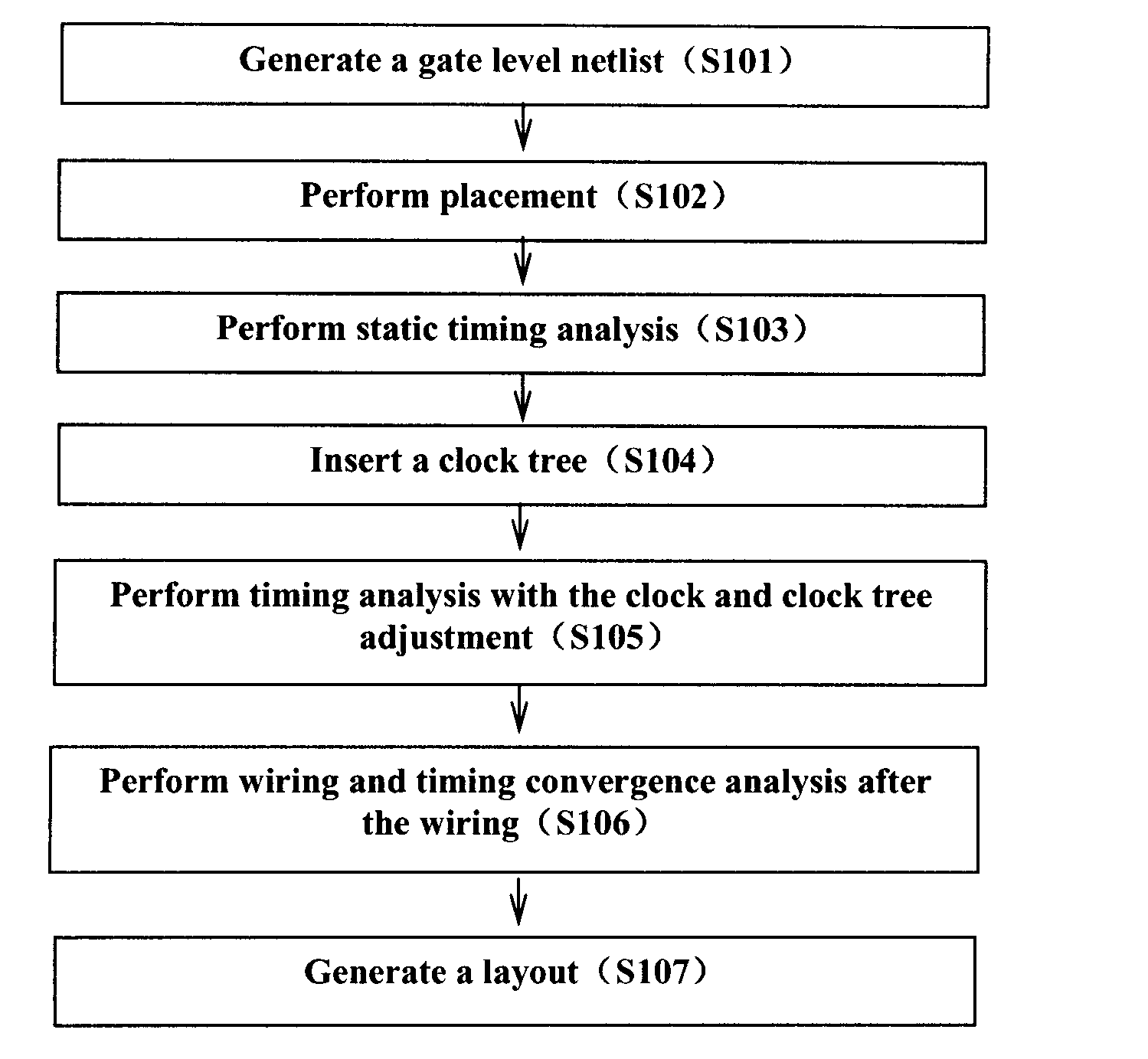
[0024]Netlist: a file or data structure to express the topological connection relationships of the devices of a digital circuit.

[0025]Clock tree: the inserted tree-shaped signal relay network formed by buffers is called a clock tree. Therefore, an ASIC usually has one or more clock trees.

[0026]Clock tree latency: it means that for a single clock t...


PUM


Abstract

The present invention discloses a method and system for clock tree planning for an ASIC, the method comprising: determining a netlist and a timing constraint file of the ASIC; creating a sequential device undirected graph for sequential devices in the netlist according to connection relationships of the sequential devices in the netlist and timing constraint relationships of the sequential devices in the timing constraint file; grouping the sequential devices in the netlist according to the sequential device undirected graph, such that the sequential devices in one group do not have a timing constraint relationship with the sequential devices in another group. The ASIC design method improved by using this method will reduce the design cycle from weeks to days, and enable designer to quickly plan the clock tree, thus reducing the design time and improving the design efficiency.

Description

FIELD OF THE INVENTION[0001]The present invention generally relates to integrated circuit design, more particularly, to a method and system for clock tree planning for an application specific integrated circuit.DESCRIPTION OF THE RELATED ART[0002]In the technical field of integrated circuits, an application specific integrated circuit (ASIC) refers to an integrated circuit which is designed and manufactured according to specific user demands and specific electronic system requirements. An ASIC is characterized in oriented to specific user demands, and during mass production, compared with general integrated circuits, it has the advantages of smaller size, lower power consumption, improved reliability, improved performance, enhanced security and reduced costs.[0003]FIG. 1 shows the flow of a current ASIC design. At step S101, a gate level netlist is generated; at step S102, full placement is performed. At step S103, static timing analysis is performed, and the step uses an ideal cloc...

Claims


Application Information

Patent Timeline
Patent Type & Authority Applications(United States)
IPC IPC(8): G06F17/50
CPCG06F2217/62G06F17/5068G06F30/39G06F30/396
Inventor GE, LIANGPU, SUOMINGXU, CHENYU, BO
Owner GLOBALFOUNDRIES INC
Why Eureka
Try Eureka