Piezoelectric resonant shunt damping for phase noise reduction

Pending Publication Date: 2021-09-30
BAE SYST INFORMATION & ELECTRONICS SYST INTERGRATION INC
View PDF0 Cites 0 Cited by
  • Summary
  • Abstract
  • Description
  • Claims
  • Application Information

AI Technical Summary

Benefits of technology

[0005]One aspect of the present disclosure is a method of reducing the motion of a vibration sensitive component, comprising: providing a structure comprising at least one vibration sensitive component; analyzing the structure to determine at least one critical mode shape and/or natural frequency of the structure to be attenuated; placing a piezoelectric device in a high strain location of the s

Problems solved by technology

Often vibration mitigation at the circuit card level comes with significant packaging or form factor design changes.
It is understood that there is inherent performance derogation due to vibration.
Firmware and/or software techni

Method used


Image

  • Piezoelectric resonant shunt damping for phase noise reduction
  • Piezoelectric resonant shunt damping for phase noise reduction
  • Piezoelectric resonant shunt damping for phase noise reduction

Examples


Example

[0023]One embodiment of the present disclosure is a system and method for addressing the improved phase noise performance of an oscillator, reduction of solder joint fatigue, and increasing circuit card survivability issues due to mechanical vibration and shock inputs to the circuit card in which said devices are mounted.

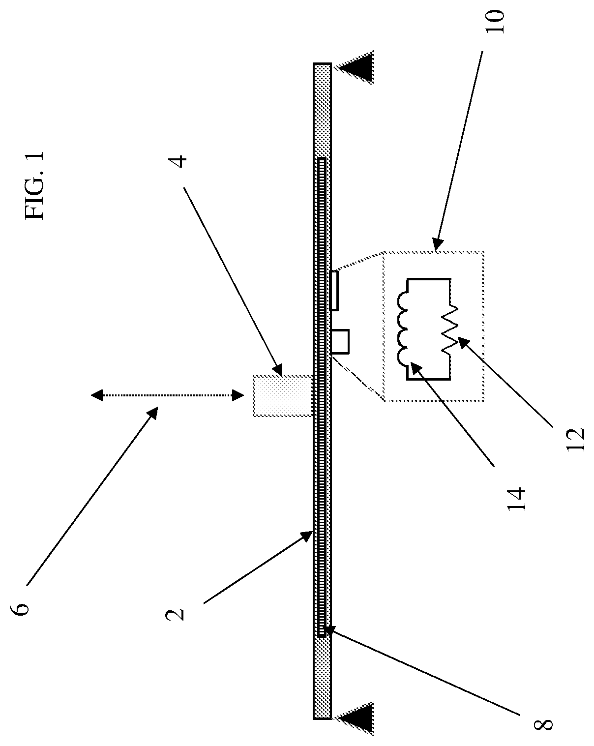
[0024]In one embodiment, a piezoelectric bending actuator is embedded within a cavity of a 3D printed circuit card assembly (CCA). In some cases, the piezoelectric bending actuator is embedded in a traditionally manufactured CCA, or some other structure to which vibration sensitive components are mounted. In other embodiments, the piezoelectric bending actuator is mounted to the surface of a structure, including, but not limited to a CCA, using epoxy or the like. When the CCA or other structure is exposed to vibration in its environment, the mechanical bending energy is converted to electrical energy via the piezoelectric device. Incorporated on the CCA or other str...


PUM


Abstract

The system and method for phase noise reduction and/or vibration reduction in assemblies using piezoelectric passive resonant shunt damping or active vibration cancellation/compensation techniques. In some cases a circuit card or similar structure comprises an embedded piezoelectric device to reduce the effects of vibration on any sensitive device or component thereon. The system has a resonant shunt circuit or other control circuit to provide electrical loading to the piezoelectric device and may be single frequency mode or multimodal. The system may also be adaptively controlled by a microprocessor or the like, so that the vibration sensitive devices are monitored and controlled over time to extend the life of the device.

Description

FIELD OF THE DISCLOSURE[0001]The present disclosure relates to phase noise or vibration reduction for oscillators, clocks, or other vibration sensitive components, and more particularly to the use of a piezoelectric bending actuator to convert mechanical bending energy to electrical energy when exposed to vibrations.BACKGROUND OF THE DISCLOSURE[0002]Traditional techniques for vibration reduction do not typically occur at the circuit card level. Often vibration mitigation at the circuit card level comes with significant packaging or form factor design changes. The technique of the present disclosure adds minimal thickness to a circuit card design, and only a few small surface mounted components. Existing solutions also tend to shift the resonant frequency, where the technique of the present disclosure simply reduces the resulting response with no natural frequency shift. Typically, compensation for phase noise is accounted for in software and firmware, rather than mechanical mitigati...

Claims


Application Information

Patent Timeline
IPC IPC(8): H01L41/04F16F15/00H01L41/09
CPCH01L41/042F16F15/007F16F15/002F16F2230/18F16F2224/0283F16F2228/066H01L41/0973G11B33/08H02N2/188H10N30/802H10N30/2047
Inventor AFFLECK, MAXWELL L.SHARP, SHAWN P.PENA, MIKEMOULTON, ALLISON
Owner BAE SYST INFORMATION & ELECTRONICS SYST INTERGRATION INC
Why Eureka
Try Eureka