Multi-size tool bit holder for a rotary power tool

a technology of power tools and tool bits, which is applied in the direction of wrenches, screwdrivers, manufacturing tools, etc., can solve the problems of requiring loosening, large, and heavy, and requiring a large amount of bit changes,

Active Publication Date: 2021-10-07
MILWAUKEE ELECTRIC TOOL CORP
View PDF0 Cites 3 Cited by
  • Summary
  • Abstract
  • Description
  • Claims
  • Application Information

AI Technical Summary

Benefits of technology

[0006]The present invention provides, in another aspect, a multi-size tool bit holder including a first sleeve having a first bit holding bore extending along an axis, and a second sleeve coupled for co-rotation with the first sleeve and movable relative to the first sleeve between a first position and a second position, the second sleeve including a second bit holding bore. The multi-size tool bit holder also includes a plurality of first retaining members movable between a first securing position in which the first retaining members project into the first bit holding bore and a first release position in which the first retaining members are withdrawn from the first bit holding bore, and a plurality of second retaining members movable between a second securing position in which the second retaining members project into the second bit holding bore and a second release position in which the second retaining members are withdrawn from the second bit holding bore. The multi-size tool bit holder also includes a collar surrounding the first sleeve and movable relative to the first sleeve between an initial position and an actuated position. The collar prevents movement of the first retaining members from the first securing position to the first release position when the collar is in the initial position, and the collar prevents movement of the second retaining members from the second securing position to the second release position when the collar is in the initial position.

Problems solved by technology

Continuously variable chucks are versatile but can be relatively heavy, large, and expensive to produce.
In addition, changing bits requires loosening and then retightening the chuck.

Method used


Image

  • Multi-size tool bit holder for a rotary power tool
  • Multi-size tool bit holder for a rotary power tool
  • Multi-size tool bit holder for a rotary power tool

Examples


Embodiment Construction

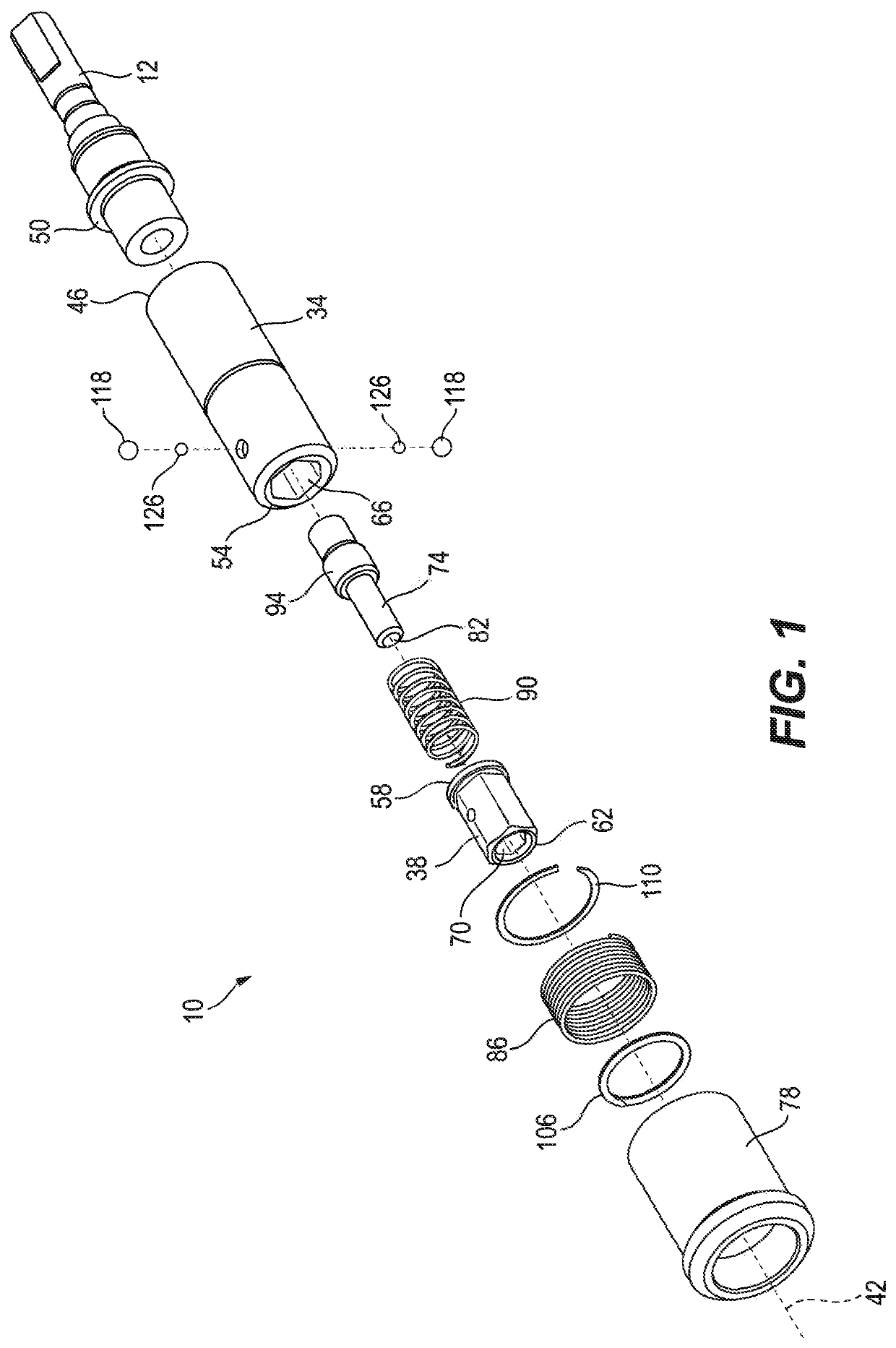
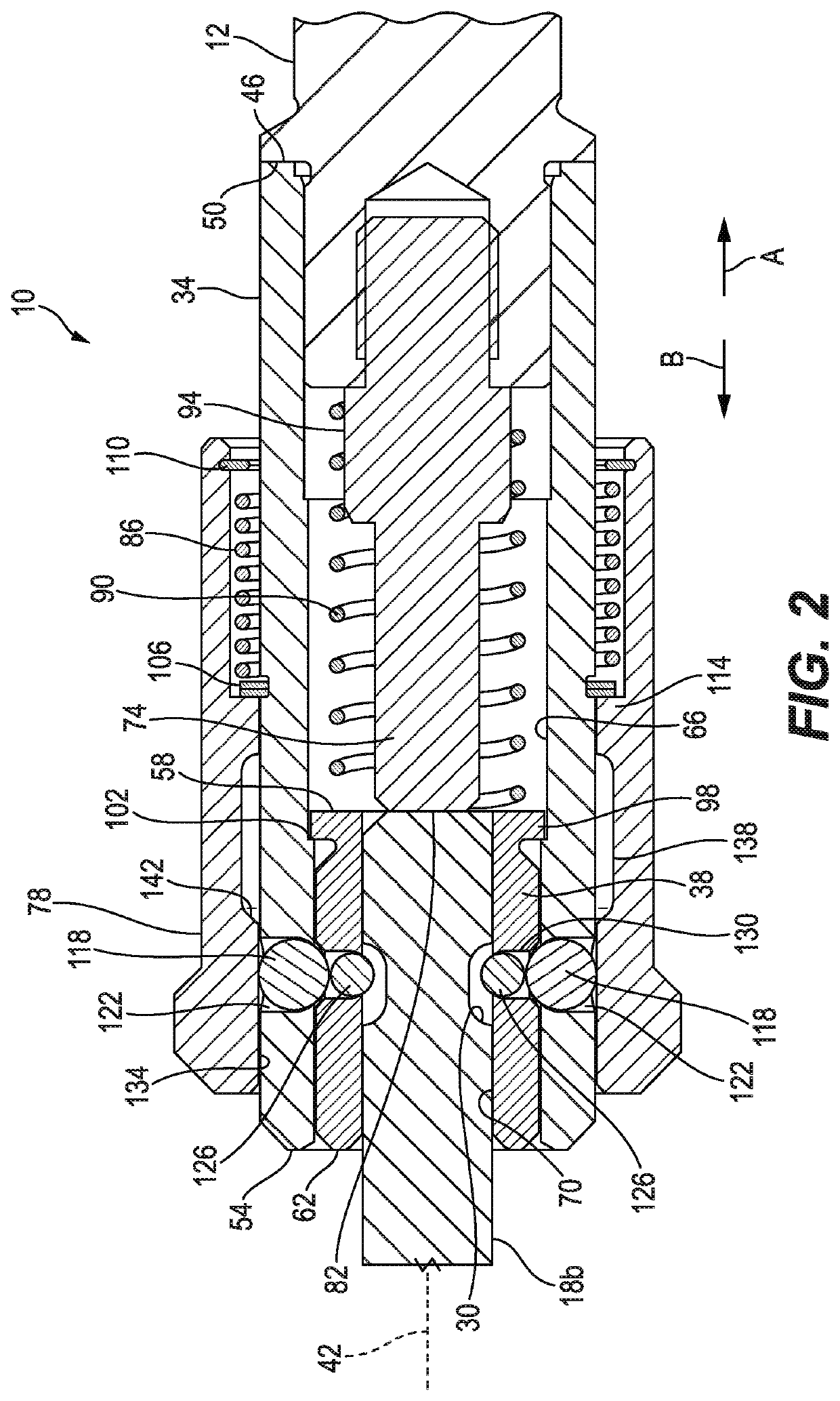
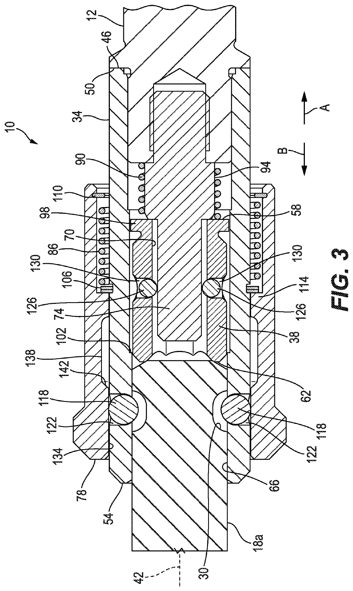
[0021]FIGS. 1-3 illustrate a tool bit holder 10 including a spindle 12 for connection to a rotational output of a rotary power tool (e.g., a drill, impact driver, etc.; not shown). The spindle 12 may be integrated into the rotary power tool and removably coupled to the remainder of the tool bit holder 10 by any suitable means. In some embodiments, the spindle 12 may be removably coupled to the rotary power tool. The bit holder 10 is configured to receive and secure tool bits with standardized shanks of at least two different predetermined, nominal sizes. For example, the illustrated bit holder 10 is configured to receive a tool bit 14 with a hexagonal shank 18 that can be either a first nominal size 22 or a second nominal size 26 (FIGS. 4 and 5). The first and second nominal sizes 22, 26 are preferably standard hexagonal shank sizes, such as 7 / 16-inch and ¼-inch, and the illustrated shank 18 also includes a groove 30. In other embodiments, the bit holder 10 may be configured to rece...


PUM


Abstract

A multi-size tool bit holder includes a first sleeve having a first bit holding bore extending along an axis, and a second sleeve coupled for co-rotation with the first sleeve and movable relative to the first sleeve between a first position and a second position. The second sleeve includes a second bit holding bore. A first bit shank of a first nominal size is insertable into the first bit holding bore when the second sleeve is in the second position to secure the first bit shank within the first sleeve. A second bit shank of a second nominal size different than the first nominal size is insertable into the second bit holding bore when the second sleeve is in the first position to secure the second bit shank within the second sleeve.

Description

CROSS-REFERENCE TO RELATED APPLICATIONS[0001]This application claims priority to co-pending U.S. Provisional Patent Application No. 62 / 743,937, filed on Oct. 10, 2018, the entire content of which is incorporated herein by reference.FIELD OF THE INVENTION[0002]The present invention relates to tool bit holders, and more particularly to tool bit holders for rotary power tools.BACKGROUND OF THE INVENTION[0003]Power tools having a rotational output (i.e. rotary power tools) typically include chuck assemblies with a plurality of jaws that are adjustable to grip and secure a tool bit (e.g., a drill bit). Some chuck assemblies are configured to accept a continuous range of bit sizes (referred to herein as “continuously variable chucks”). Continuously variable chucks are versatile but can be relatively heavy, large, and expensive to produce. In addition, changing bits requires loosening and then retightening the chuck. Other chuck assemblies or tool bit holders are configured to accept one s...

Claims


Application Information

Patent Timeline
Patent Type & Authority Applications(United States)
IPC IPC(8): B25B23/00
CPCB25B23/0035B23B31/1071
Inventor ABBOTT, JONATHAN E.
Owner MILWAUKEE ELECTRIC TOOL CORP
Why Eureka
Try Eureka