Heat exchanger for a turbomachine and manufacturing thereof

a technology of heat exchanger and turbomachine, which is applied in the direction of machines/engines, light and heating apparatus, laminated elements, etc., can solve the problems of compact assembly and achieve the effect of simplifying assembly operation

Active Publication Date: 2021-10-07
SN DETUDE & DE CONSTR DE MOTEURS DAVIATION S N E C M A
View PDF0 Cites 0 Cited by
  • Summary
  • Abstract
  • Description
  • Claims
  • Application Information

AI Technical Summary

Benefits of technology

[0013]According to the invention, the fluid connection at one end of the exchanger is made directly inside the annular part since the first circuit and the second circuit are formed in it. In contrast to the previous technique, there is no need for welded or brazed connection parts. In addition, the conformation of the first sealing member so as to allow fluid continuity within the first circuit and the second circuit simplifies the assembly operation, as only one member is required at this point. This assembly is also very compact.

Problems solved by technology

This assembly is also very compact.

Method used


Image

  • Heat exchanger for a turbomachine and manufacturing thereof
  • Heat exchanger for a turbomachine and manufacturing thereof
  • Heat exchanger for a turbomachine and manufacturing thereof

Examples


Embodiment Construction

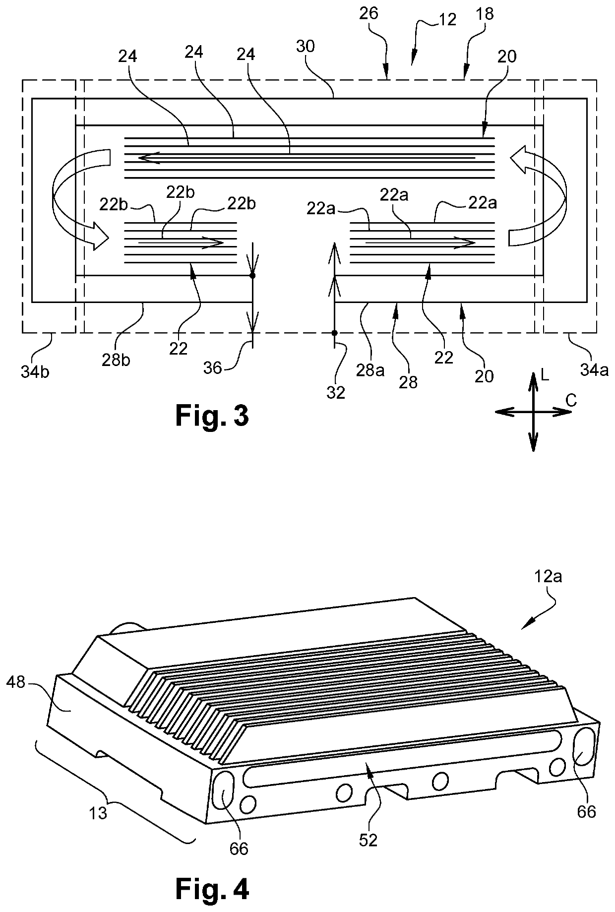
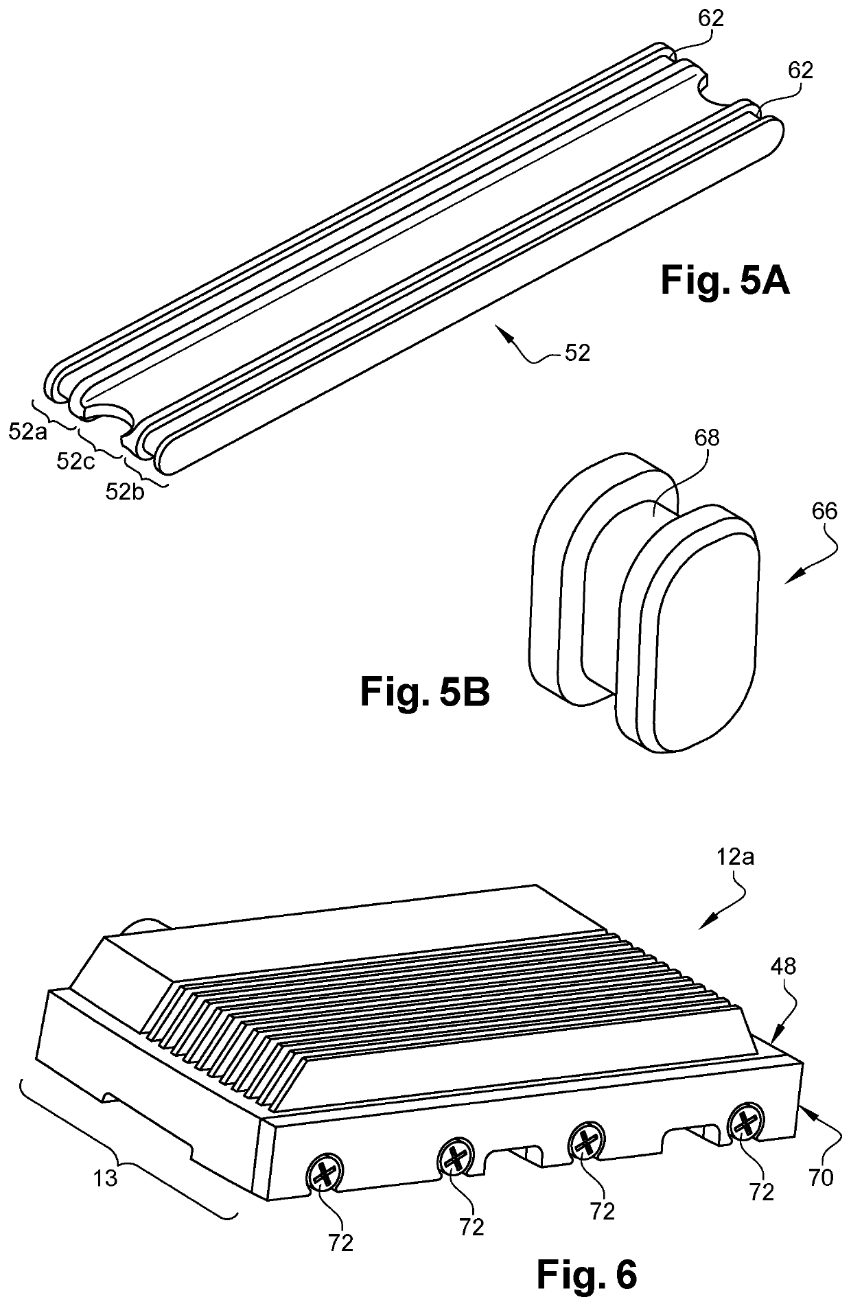
[0028]Reference is now made to FIGS. 4 to 8 which represent a heat exchanger according to the invention. Similarly to what has been described with reference to FIG. 3, the exchanger 12a also comprises a first fluidic circuit 37 of oil comprising a plurality of first conduits 38 and second conduits 40 substantially parallel to each other, the first conduits 38 comprising first and second portions 38a. The exchanger 12a also comprises a second thawing fluid circuit 42 comprising a first conduit 44 and a second conduit 46 which are parallel, the first conduit 44 comprising a first portion 44a and a second portion.

[0029]The first conduits 38, 44 and second conduits 40, 42 of the first and second circuits 37, 42 are quite similar to what has been described previously with reference to FIG. 3 and differ from them only in their fluid connection to each other at the circumferential ends of the heat exchanger. Also, what will be described with reference to the first circumferential end 13 of...


PUM


Abstract

An annular heat exchanger with a longitudinal axis for a turbomachine, intended for example to be supported by an annular shell of a casing of the turbomachine, includes a one-piece annular part having a first fluidic circuit having at least one first conduit and at least one second conduit extending annularly and a second fluidic circuit having at least one first conduit and at least one second conduit extending annularly and arranged in a direction perpendicular to the longitudinal direction on either side of the first conduit and second conduit of the first circuit.

Description

FIELD OF THE INVENTION[0001]The present invention relates to a heat exchanger and more particularly the cooling of the oil in an aircraft engine.BACKGROUND OF THE INVENTION[0002]FIG. 1 represents a turbomachine 10 with double flow which comprises moving parts which rub against other moving parts or against fixed parts, this connection is for example a bearing. In order not to break due to heating due to friction, the parts are sprayed with oil which allows on the one hand to limit (or contain) their heating and, on the other hand, to lubricate them to facilitate the sliding of the parts on top of each other.[0003]The oil circulates in a circuit provided with heat exchangers, in particular oil / air exchangers 12, as shown in FIG. 2, having a matrix, in the form of a sinuous pipe shaped so as to carry out an exchange of heat, in which the oil from said parts is introduced then cooled before being injected again on said parts. The heat exchanger 12 shown in FIG. 2 is an annular heat exc...

Claims


Application Information

Patent Timeline
Patent Type & Authority Applications(United States)
IPC IPC(8): F02C7/14F28F3/12
CPCF02C7/14F05D2260/213F05D2220/323F28F3/12F28D9/00F28D2021/0089F28F2220/00F28D2021/0049F28F2230/00F28D7/0066F28D2021/0026F28D2021/0021
Inventor BLUM, HERVÉ EUGÈNEGUILLOU, LANCELOT
Owner SN DETUDE & DE CONSTR DE MOTEURS DAVIATION S N E C M A
Why Eureka
Try Eureka