
Support structure for wind-driven power generators

a technology of supporting structure and wind power generator, which is applied in the direction of buildings, buildings, buildings, etc., can solve the problems of complex operation, increased labor, and large and achieves the effect of reducing the size of the wall piece and therefore its weight, facilitating handling and installation, and simplifying assembly operations

Active Publication Date: 2021-03-25
PACADAR
View PDF0 Cites 0 Cited by
  • Summary
  • Abstract
  • Description
  • Claims
  • Application Information

AI Technical Summary

Benefits of technology

The patent text describes a method of strengthening tubular towers against wind loads by using post-tensioning cables. These cables are placed inside or outside of the tower and press the wall pieces together, compressing them. This increases the resistance of the tower to horizontal wind loads. However, small errors in the dimensions of the wall pieces can cause the tower to become less vertical, which negatively impacts its strength. The patent aims to address this issue and improve the stability of the tower.

Problems solved by technology

This complicates the manufacturing, transport and lifting of said wall pieces, leading to more expensive labor.
This requires the wall pieces to include structural reinforcements designed for channeling stresses to those points in which the structural connectors will be installed, complicating the manufacturing thereof, and requires performing tasks of making structural connection in each annular section by means of said structural connectors, requiring complicated operations that must be performed at a great height.
For example, post-tensioning requires specific machinery that must be lifted to the position where said post-tensioning is performed, and structural screws are large screws that an operator can hardly lift by hand, or must be lifted one by one or in small quantities, slowing down the installation thereof, and the injection of mortar requires using pumping machines and formworks making the commissioning more expensive and slowing it down.
Furthermore, this patent document does not contemplate complete post-tensioning of the entire tubular tower in the entire length thereof, but rather uses local post-tensioning in each transverse joint of the tubular tower, this being the reason why the number of transverse joints is kept small by using wall pieces having a large size.
All these features make manufacturing the wall pieces, as well as the tasks of assembling them, difficult and more expensive.
This means that even if each annular section is formed by only two wall pieces, each of them will have a height greater than twice its width, where these wall pieces are therefore very tall with a small base, and when subjected to a horizontal load at the upper end thereof, will generate a large bending moment that their base can hardly sustain without the structural collaboration of the adjoining wall pieces.
However, this patent document proposes for all the wall pieces to be attached by means of screws to the upper, lower and side wall pieces, thereby achieving an integral assembly, which requires a large number of screwed attachments, complicating the assembly of the structure and slowing it down.

Method used


Image

  • Support structure for wind-driven power generators
  • Support structure for wind-driven power generators
  • Support structure for wind-driven power generators

Examples


Embodiment Construction

[0076]The attached drawings show illustrative non-limiting embodiments of the present invention.

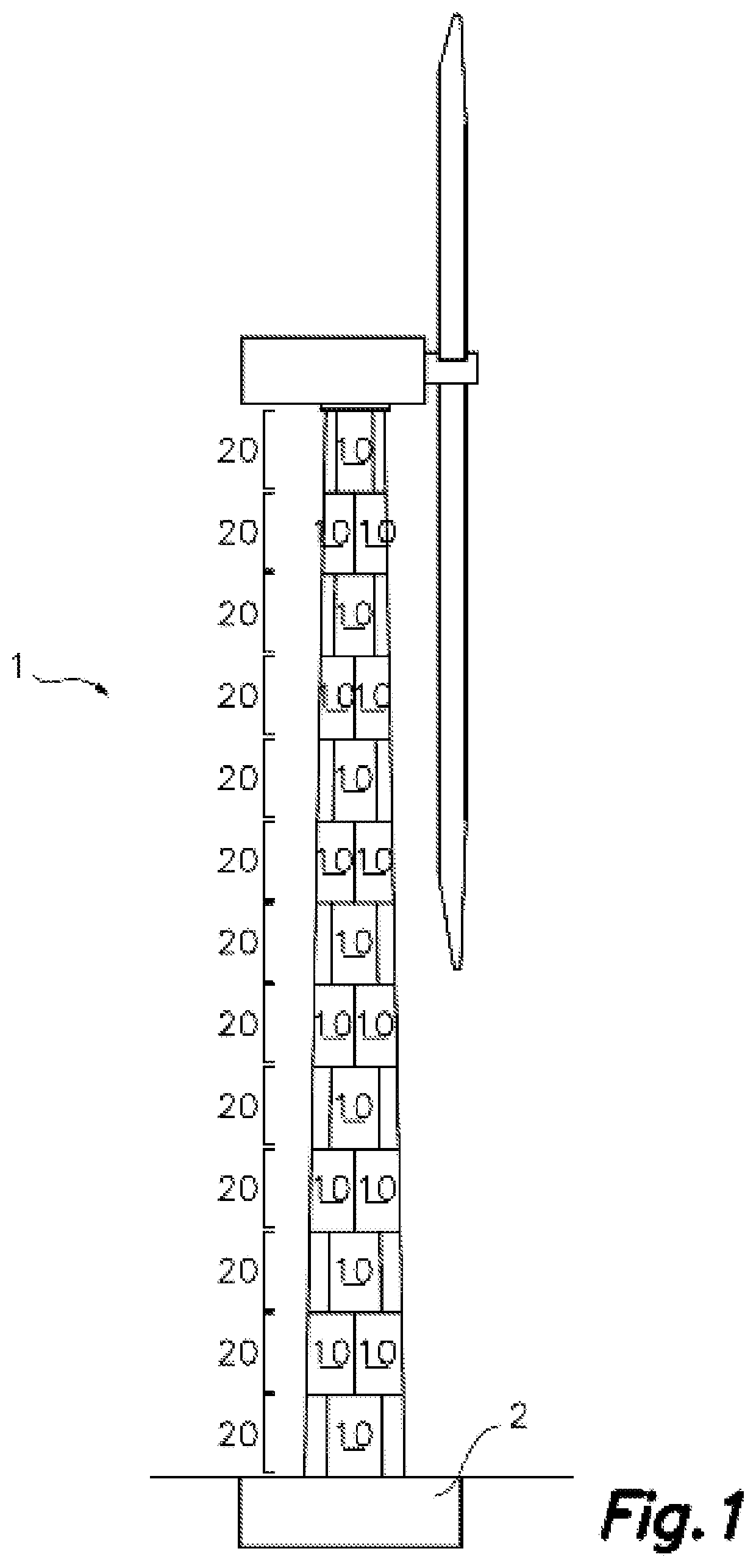
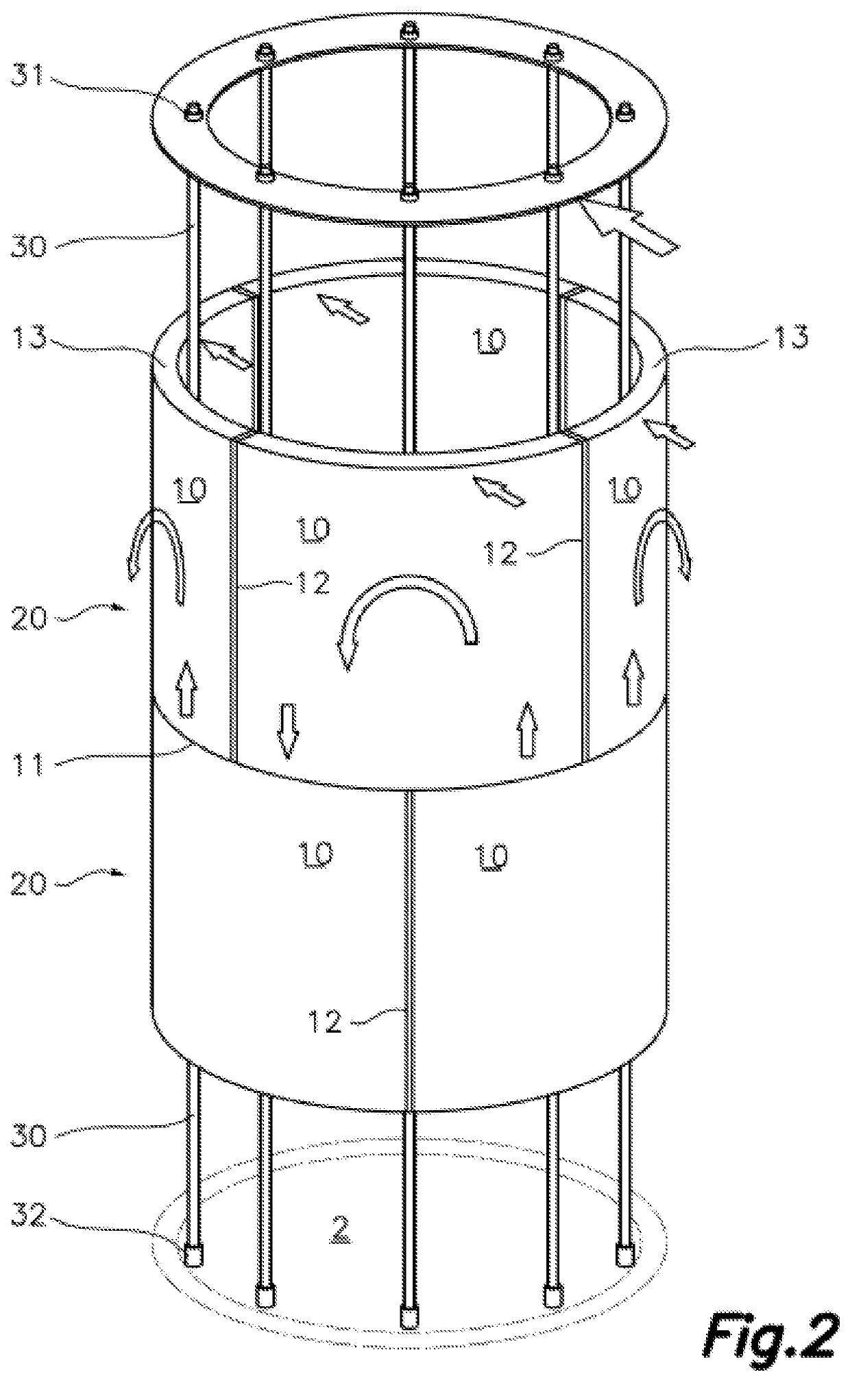
[0077]FIG. 1 shows a support structure for wind-driven power generators formed by multiple superposed annular sections 20 having a frustoconical section, a tubular tower 1 having a hollow inner space with an increasingly smaller cross-section thus being obtained.

[0078]Each annular section 20 is formed by multiple wall pieces 10 each with a cross-section in the form of annular section, such that a circular annular section is formed upon putting together all the wall pieces 10.

[0079]As it is obvious for a skilled person, if the wall pieces 10 have a cross-section in the form of a polygonal section, the annular section formed by said pieces will also have a closed polygonal section in the form of a tube.

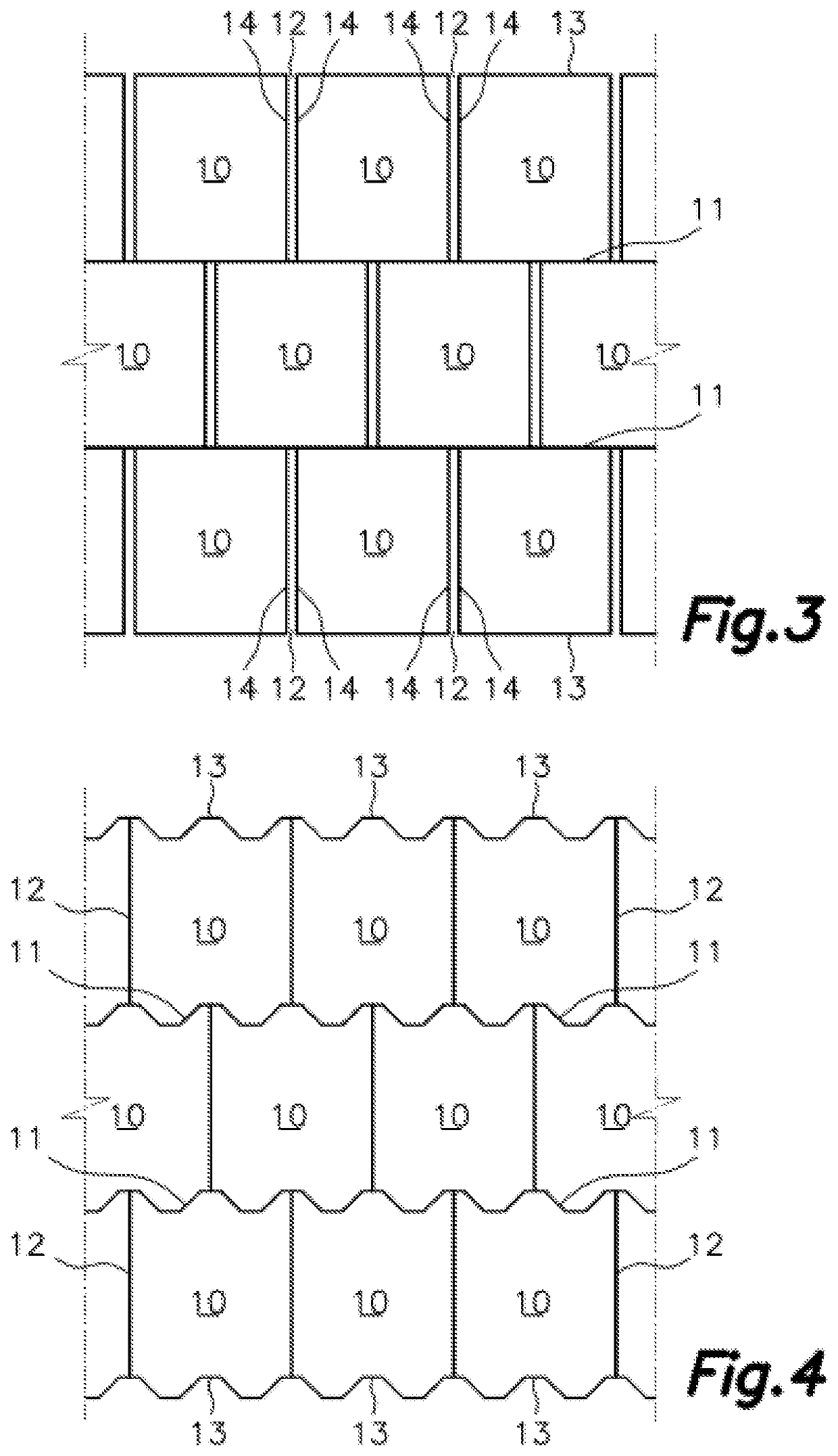
[0080]The joints existing between superposed annular sections 20 are transverse joints 11, whereas the joints existing between the adjacent wall pieces 10 of one and the same annular section ...


PUM


Abstract

The present invention relates to a support structure for wind-driven power generators comprising a tubular tower (1) with multiple superposed, post-tensioned annular sections (20) from the crown to the foundation, each being formed by at least two pieces of prefabricated concrete wall (10) defining between them vertical joints (12), each wall piece (10) having two transverse joint faces (13) and two vertical joint faces (14); wherein in the vertical joints (12), the vertical joint faces are arranged facing one another and lack structural connectors between them for the transmission of structural stresses, allowing for an independent structural behavior of the mentioned wall pieces (10), the height of the wall pieces (10) being less than twice their width.

Description

FIELD OF THE ART[0001]The present invention relates to the field of support structures for wind-driven power generators provided with a tower made up of wall pieces of prefabricated concrete attached to one another forming superposed annular sections that are subsequently post-tensioned.STATE OF THE ART[0002]Support structures for wind-driven power generators obtained by means of stacking annular sections made up of wall pieces of prefabricated concrete are known.[0003]PACADAR's patent document EP2631393, for example, is known to describe a system of this type, but in which the wall pieces of each annular section have a great height, the entire tubular tower being made up of a few, for example, three, four or five, annular sections. This complicates the manufacturing, transport and lifting of said wall pieces, leading to more expensive labor.[0004]Furthermore, the proposed solution in this patent document requires the wall pieces of one and the same annular section to be laterally c...

Claims


Application Information

Patent Timeline
Patent Type & Authority Applications(United States)
IPC IPC(8): F03D13/20
CPCF03D13/20F05B2260/301F05B2240/912E04H12/12E04H12/16E04H12/342Y02E10/72
Inventor LANCHA FERNANDEZ, JUAN CARLOSCIDONCHA ESCOBAR, MANUELSALETE CASINO, EDUARDOMARTINEZ DE CASTANEDA, FRANCISCO JAVIER
Owner PACADAR
Learn More