Integrated drive for bicycle handlebars

a technology of integrated drive and handlebars, which is applied in the direction of cycle control systems, cycle equipments, cycle brakes, etc., can solve the problems of general bulky drive of these systems, and achieve the effect of simplifying the assembly operation of the handlebars and reducing the bulk of the overall system

Active Publication Date: 2020-06-09
CAMPAGNOLO SRL
View PDF47 Cites 0 Cited by
  • Summary
  • Abstract
  • Description
  • Claims
  • Application Information

AI Technical Summary

Benefits of technology

[0008]Such a drive, which encloses in the same grip body not only all what is needed to drive the hydraulic brake, but also drives for the gearshift, allows the overall bulk to be significantly reduced. Moreover, it also allows a simplification of the assembly operations of the handlebars, since the driving functions of two systems, the braking system and the speed gear, can be included in a single drive.

Problems solved by technology

However, the drives for the actuators of these systems are generally bulky, to the extent as to often be undesirable to the most demanding users.

Method used


Image

  • Integrated drive for bicycle handlebars
  • Integrated drive for bicycle handlebars
  • Integrated drive for bicycle handlebars

Examples


first embodiment

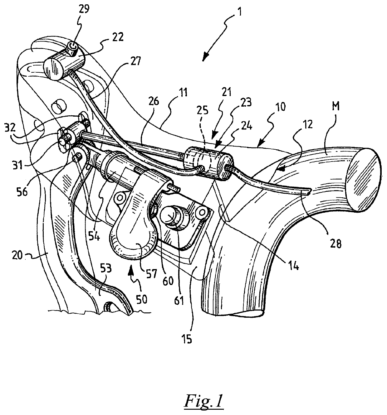
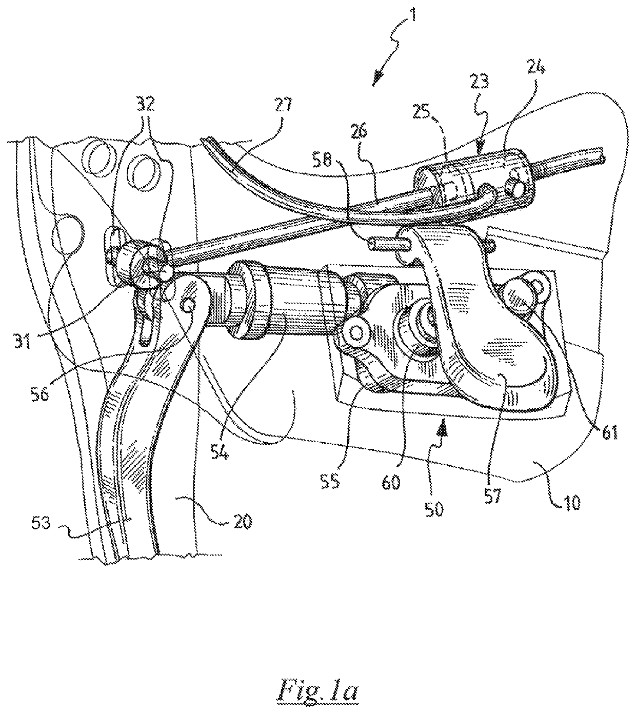
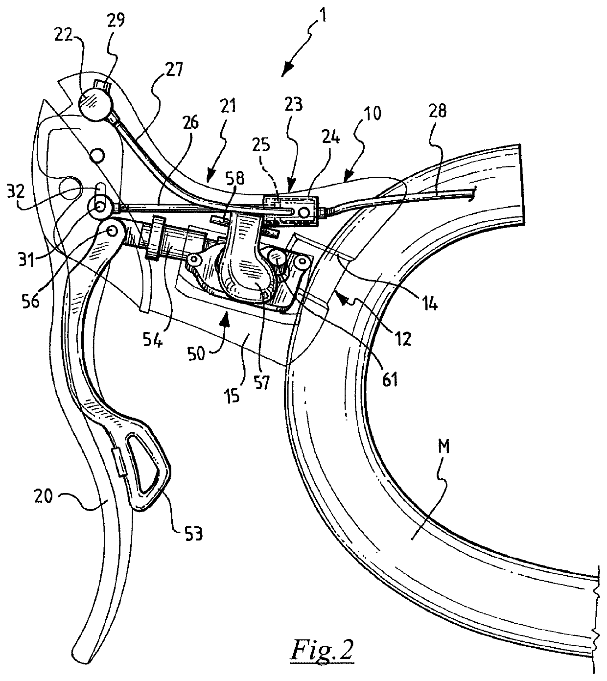
[0030]In the Figures, reference numeral 1 wholly indicates an integrated drive according to the invention. The integrated drive 1 is intended to be mounted on one of the ends of bicycle handlebars M (shown partially only in FIGS. 1 and 2 together with the invention), to drive a hydraulic brake and a derailleur of the bicycle; the handlebars M are of the type with curved ends. Normally, two integrated drives 1 will be mounted on the handlebars M, at the two opposite ends, so as to drive the two brakes (front and rear) and the two derailleurs (front and rear) of the bicycle.

[0031]The integrated drive 1 comprises a grip body 10, which has a shape and size such as to be able to be gripped by the cyclist while riding the bicycle. The grip body 10 comprises a hollow casing 11 provided with a rear face 12 on which to rest and fix to the handlebars M.

[0032]The integrated drive 1 comprises a strap 13 for mounting on the handlebars M. The strap 13 is arranged in a suitable seat 14 formed on t...

second embodiment

[0034]Inside the grip body 10 of the integrated drive 1, a hydraulic system 21 is mounted, actuated mechanically by the brake lever 20 to send pressurised fluid in a braking system of the bicycle. In one embodiment, the hydraulic system 21 is an oil-hydraulic system. More specifically, the hydraulic system 21 comprises a tank 22 for collecting operative fluid (typically oil, not shown in the drawings) and a cylinder-piston group 23 for the pressurisation of the operative fluid, in turn comprising a cylinder 24 and a piston 25, able to slide in a sealed manner in the cylinder 24 and provided with a stem 26. The cylinder 24 is mounted fixed in the grip body 10, but it could also be mounted hinged to the grip body 10, in an embodiment that is not illustrated. The hydraulic system 21 also comprises a supply tube 27 of non-pressurised operative fluid between the tank 22 and the cylinder-piston group 23 and a delivery tube 28 of pressurised operative fluid coming out from the cylinder-pis...


PUM


Abstract

An integrated drive for bicycle handlebars comprising a grip body having a shape and size suitable for being gripped by the cyclist in a holding condition while riding, a brake lever carried by the grip body, a hydraulic system mounted inside the grip body and mechanically actuated by the brake lever to send pressurised fluid into a braking system, and a set of gearshift drives, on said grip body. Such a drive, which encloses in the same grip body not only all that is needed to drive the hydraulic brake, but also drives for the gearshift and allows the overall bulk to be significantly reduced.

Description

CROSS REFERENCE TO RELATED APPLICATION(S)[0001]This application claims the benefit of Italian Application No. MI2013A001933, which was filed on Nov. 20, 2013, and is incorporated herein by reference as if fully set forth.FIELD OF INVENTION[0002]The present invention concerns an integrated drive for bicycle handlebars; in the technical field of bicycle equipment, by integrated drive it is normally meant a single drive that comprises both means for driving a brake, and means for driving a gearshift of a bicycle.BACKGROUND[0003]In modern bicycles, in particular high performance ones, there is increasing use of oil-hydraulic actuators and electric actuators.[0004]In particular, disc brake systems are known, in which braking is obtained by means of the closing of calipers on the discs; the force necessary to obtain adequate braking by means of closing calipers on the discs is produced by an oil-hydraulic group, for which reason these braking systems are commonly called hydraulic brakes. ...

Claims


Application Information

Patent Timeline
Patent Type & Authority Patents(United States)
IPC IPC(8): B62L3/00B62L3/02B62K23/02B62M25/08F16D121/02
CPCB62L3/023B62K23/02B62M25/08Y10T74/20396F16D2121/02
Inventor DAL PRÀ, GIUSEPPE
Owner CAMPAGNOLO SRL
Why Eureka
Try Eureka