Network management system for federated multi-site logical network

a network management system and multi-site technology, applied in the field of network management system for managing a logical network, to achieve the effect of minimizing the amount of data

Pending Publication Date: 2021-10-07
VMWARE INC
View PDF58 Cites 18 Cited by
  • Summary
  • Abstract
  • Description
  • Claims
  • Application Information

AI Technical Summary

Benefits of technology

[0025]When providing updates to the logical network state data, in some embodiments the controllers do not re-send entire lists of MAC addresses for a given logical switch or entire lists of addresses for a particular security group between sites. Instead, some embodiments send each change to the current state as an atomic update specifying the change, thereby minimizing the amount of data that needs to be transferred between sites. The controllers at a particular site maintain a snapshot of the current logical network state (e.g., in a distributed database at the site), and whenever this state changes (e.g., due to creation or deletion of a DCN from a host computer in the site), each controller that handles sending that state to another site identifies the change and sends the change as an update to the other site. Because these changes can be derived by any of the controllers in the cluster at the sending site, this site does not persist the queue of updates in some embodiments. In some embodiments, the synchronization protocol is lossless, so once an update is sent from a first site to a second site it can be assumed that the second site will process that update (and will do so in the order that the updates are received). In addition, the controllers at the second site persist these updates in a distributed database.

Problems solved by technology

While logical networks that operate within a single site are well established, there are various challenges in having logical networks span multiple physical sites (e.g., datacenters).

Method used


Image

  • Network management system for federated multi-site logical network
  • Network management system for federated multi-site logical network
  • Network management system for federated multi-site logical network

Examples


Embodiment Construction

[0062]In the following detailed description of the invention, numerous details, examples, and embodiments of the invention are set forth and described. However, it will be clear and apparent to one skilled in the art that the invention is not limited to the embodiments set forth and that the invention may be practiced without some of the specific details and examples discussed.

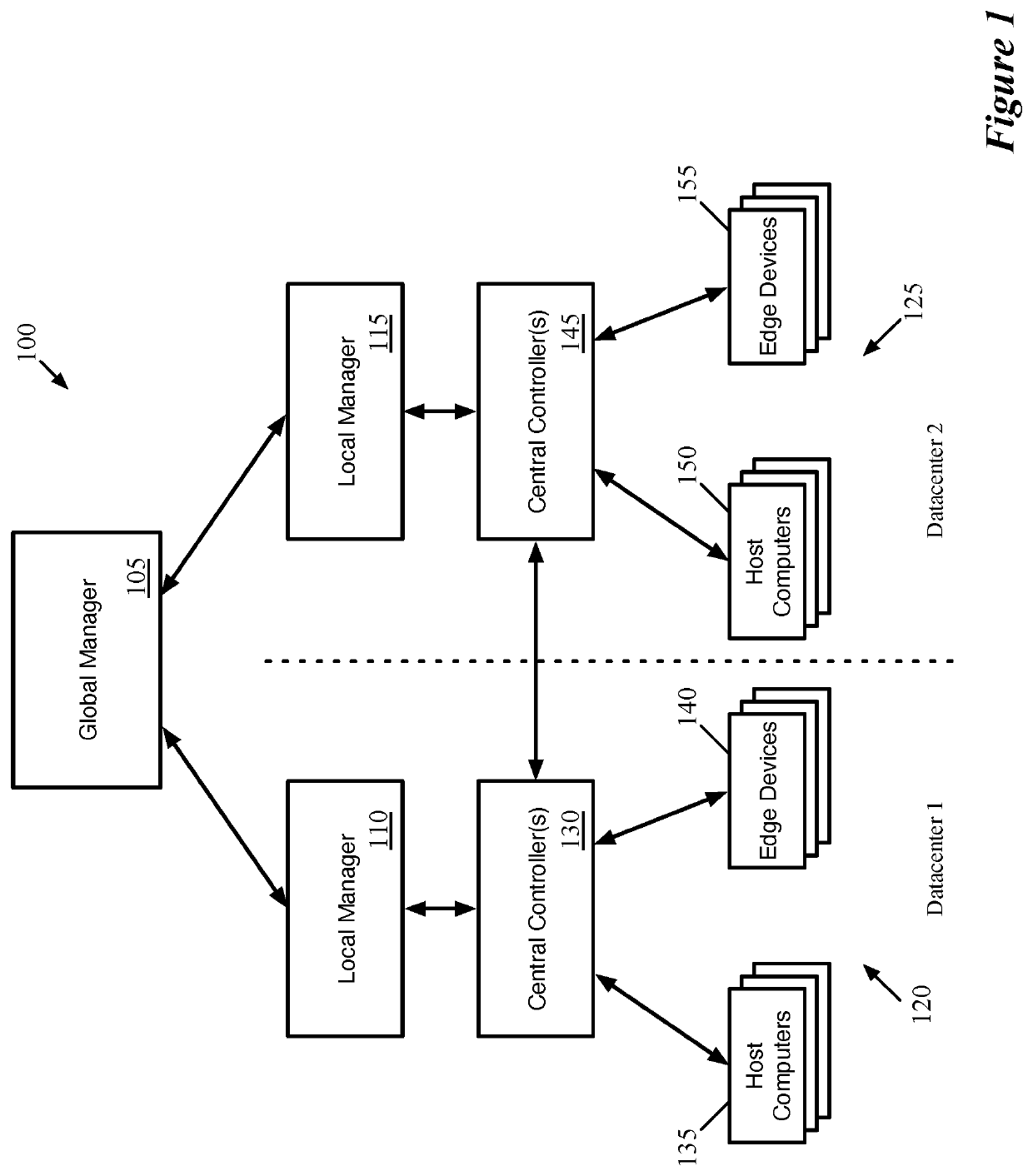
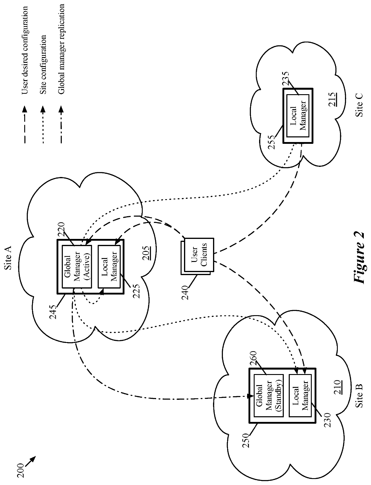
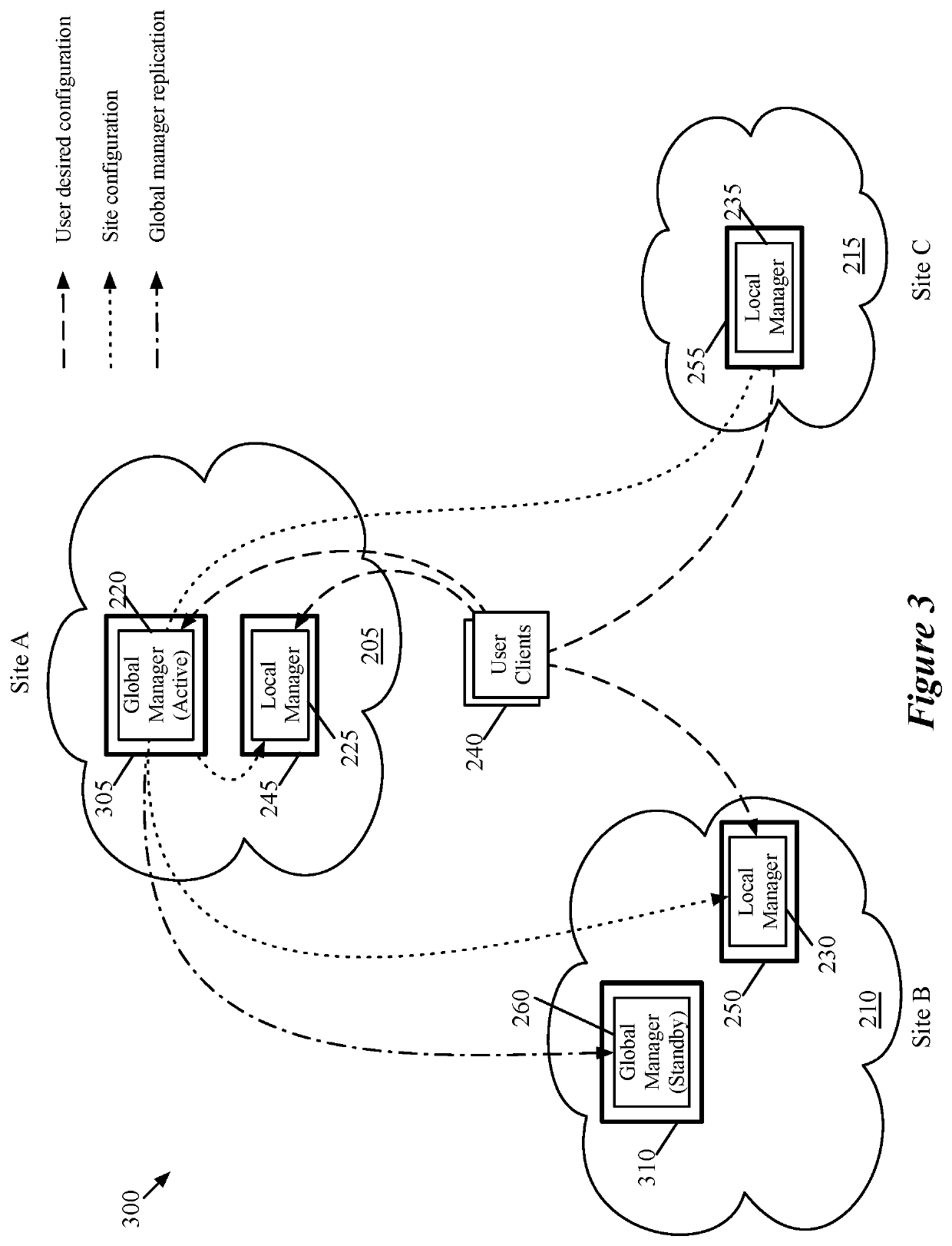
[0063]Some embodiments of the invention provide a network management system for managing a logical network spanning multiple federated physical sites (e.g., multiple datacenters). The network management system of some embodiments includes (i) a global network manager that manages the entire logical network spanning all of the sites, (ii) local network managers at each site that directly manage the logical network at their respective sites, and (iii) central controllers at each site for distributing logical network configuration data to computing devices at the site that implement the logical network. The globa...


PUM


Abstract

Some embodiments provide a network management system for managing a logical network that spans multiple physical sites. The network management system includes a global network manager for receiving global logical network configuration data for the multiple physical sites. The network management system includes, at each of the physical sites, (i) a local network manager for receiving a logical network configuration for the physical site from the global network manager and (ii) a set of central controllers for distributing logical network configuration data to computing devices that implement the logical network at the physical site.

Description

BACKGROUND[0001]As more networks move to the cloud, it is more common for one corporation or other entity to have networks spanning multiple sites. While logical networks that operate within a single site are well established, there are various challenges in having logical networks span multiple physical sites (e.g., datacenters). The sites should be self-contained, while also allowing for data to be sent from one site to another easily. Various solutions are required to solve these issues.BRIEF SUMMARY[0002]Some embodiments of the invention provide a network management system for managing a logical network spanning multiple federated sites (e.g., multiple datacenters). The network management system of some embodiments includes (i) a global network manager that manages the entire logical network spanning all of the sites, (ii) local network managers at each site that directly manage the logical network at their respective sites, and (iii) central controllers at each site for distrib...

Claims


Application Information

Patent Timeline
Patent Type & Authority Applications(United States)
IPC IPC(8): H04L12/24H04L29/06
CPCH04L41/0213H04L63/0209H04L41/0893H04L41/0846H04L41/042H04L41/12H04L41/0869H04L41/22H04L41/0663H04L41/044H04L41/0894H04L41/40H04L41/0895G06F3/0482H04L67/1095H04L67/289H04L41/02H04L41/0246H04L41/085H04L41/0873H04L43/04H04L43/06H04L61/103
Inventor CHANDRASHEKHAR, GANESANTHAKKAR, PANKAJMARGARIAN, PAVLUSH
Owner VMWARE INC
Why Eureka
Try Eureka