
Small hydraulic leak detection and related methods

a technology for hydraulic leak detection and related methods, applied in fluid tightness measurement, instruments, braking systems, etc., can solve problems such as inability to detect leaks, inability to achieve haptic feedback signals, and inability to transmit haptic feedback signals from the brake circuit to the brake pedal

Active Publication Date: 2021-10-14
CONTINENTAL AUTOMOTIVE SYST INC
View PDF7 Cites 3 Cited by
  • Summary
  • Abstract
  • Description
  • Claims
  • Application Information

AI Technical Summary

Benefits of technology

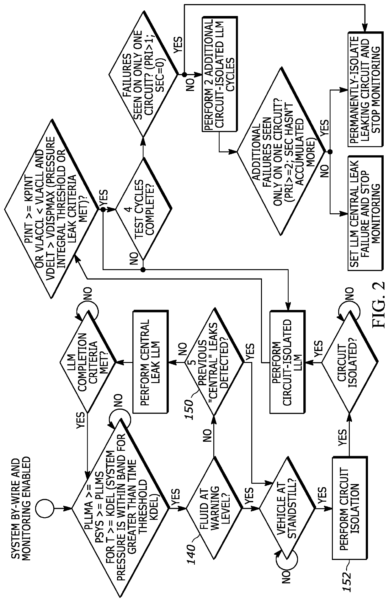
The present patent describes a method for detecting small hydraulic leaks in a vehicle that has several braking circuits. The method involves monitoring the system braking pressure and detecting if any leakage exists in the braking circuits. If a leakage is detected, the circuit is isolated to prevent the leakage from spreading. The method also includes determining if a predetermined leakage level is met or if the leakage is above a certain level. Additionally, if there are multiple leakage failures, a central leak failure is set and monitoring is ceased. Overall, the method helps to quickly detect and fix small hydraulic leaks in braking circuits, ensuring safe driving.

Problems solved by technology

Such brake systems comprise a large number of hydraulic lines, which are interconnected by the valves in different ways, and therefore the occurrence of leaks cannot be excluded.
Particularly in the case of “brake-by-wire” brake systems, there is the disadvantage that haptic feedback signals from the brake circuits are not transmitted to the brake pedal when said brake circuits are separated from the master brake cylinder.
However, the disadvantage here is that it is not possible to achieve haptic feedback signals which indicate to the driver the safety and integrity of the brake system.
The variations in pedal force (albeit, small) could potentially have ill effects on the accuracy and precision of the measurement / detection of small leaks (meaning those less than the minimum-detectable range of leaks during a normal in-motion brake apply).
The location of the leak(s) have potential to cause destabilization of a highly-loaded and / or imbalanced vehicle (imbalanced in the sense of loads being distributed away from the center of mass).

Method used


Image

  • Small hydraulic leak detection and related methods
  • Small hydraulic leak detection and related methods

Examples


Embodiment Construction

lass="d_n">[0025]The following detailed description includes references to the accompanying drawings, which form a part of the detailed description. The drawings show, by way of illustration, specific embodiments in which the apparatus may be practiced. These embodiments, which are also referred to herein as “examples” or “options,” are described in enough detail to enable those skilled in the art to practice the present embodiments. The embodiments may be combined, other embodiments may be utilized, or structural or logical changes may be made without departing from the scope of the invention. The following detailed description is, therefore, not to be taken in a limiting sense and the scope of the invention is defined by the appended claims and their legal equivalents.

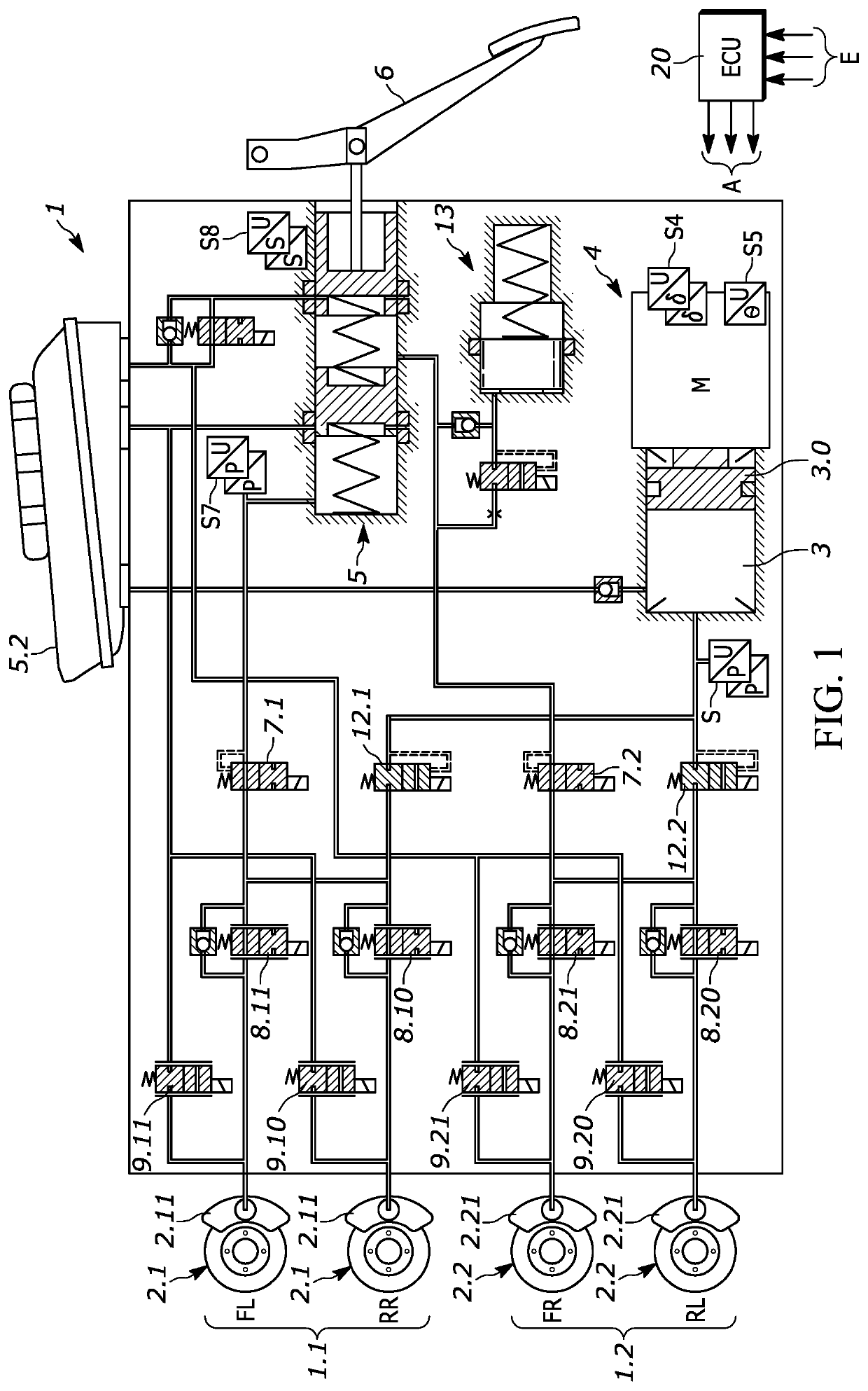
[0026]The brake system 1 shown in FIG. 1 comprises —a master brake cylinder 5 that can be actuated by means of a brake pedal 6, a displacement simulator 13 interacting with the master brake cylinder 5, —a pressure me...


PUM


Abstract

A method for detecting a small hydraulic leak of braking fluid in a vehicle, the vehicle having at least a first braking circuit and a second braking circuit, the method includes determining whether system braking pressure falls within a predetermined range, determining whether leakage exists in the braking circuits, determining whether the vehicle is in secure standstill, monitoring small leakage of a braking circuit while the vehicle is in secure standstill if leakage was detected and the vehicle is in the secure standstill, and isolating at least one of the braking circuits if a leakage exists in one of the braking circuits.

Description

TECHNICAL FIELD[0001]The disclosure herein relates to a system for detecting small hydraulic leaks within a braking system.TECHNICAL BACKGROUND[0002]Two-axle vehicles are fitted with hydraulic systems that have two brake circuits, thus ensuring that, if one of the two brake circuits fails, the vehicle can still be braked by means of the other brake circuit. In general, the wheel brakes are associated with the brake circuits in a diagonally split arrangement, in which a brake circuit acts on one front wheel and the respective diagonally opposite rear wheel. The two brake circuits are connected to a master brake cylinder, to which a brake pedal actuated by a driver to build up a corresponding brake pressure in the two brake circuits is coupled.[0003]To implement a “brake-by-wire” brake system with a fallback level, a displacement simulator, an electrically controllable pressure source, two block valves (also referred to as connecting valves) and two circuit block valves are required i...

Claims


Application Information

Patent Timeline
IPC IPC(8): G01M3/26B60T17/22
CPCG01M3/26B60T17/221B60T2270/404B60T2270/406B60T2270/402B60T13/686B60T13/745B60T7/042B60T13/662G01M3/2846B60T2270/403B60T2270/88
Inventor ROSENBERG, LEESHETTY, KEERTHANHAGEN, KYLE
Owner CONTINENTAL AUTOMOTIVE SYST INC
Learn More