Emergency respiratory ventilator

Active Publication Date: 2021-10-21
VENTI NOW
0 Cites 0 Cited by

AI-Extracted Technical Summary

Problems solved by technology

In emergency situations wherein civilian/human respiratory failure occurs due, for example, to a pandemic, a widespread danger to public health is presented.
Hospital equipment is often fully exhausted with respect to respiratory problems, particularly with respect to ventilators.
Although the '282 patent discloses an interesting device, it is quite complicated and would be rather expensive and, therefore, not adequate to meet the need in emergency management scenarios.
The '282 patent discloses a fairly com...

Benefits of technology

[0026]Another aspect of the innovation is the inclusion of a flow sensor to which the patient breathing circuit attaches. This allows for the monitoring of airflow to the patient and integration of the tidal volume of a...

Abstract

An emergency respirator ventilator that comprising an air cylinder and piston/piston rod for compressing an air bag to transmit air to a patient, e.g., during situations where fully equipped ventilators are not immediately available.

Application Domain

RespiratorsMedical devices

Technology Topic

EngineeringIntensive care medicine +3

Image

  • Emergency respiratory ventilator
  • Emergency respiratory ventilator
  • Emergency respiratory ventilator

Examples

  • Experimental program(1)

Example

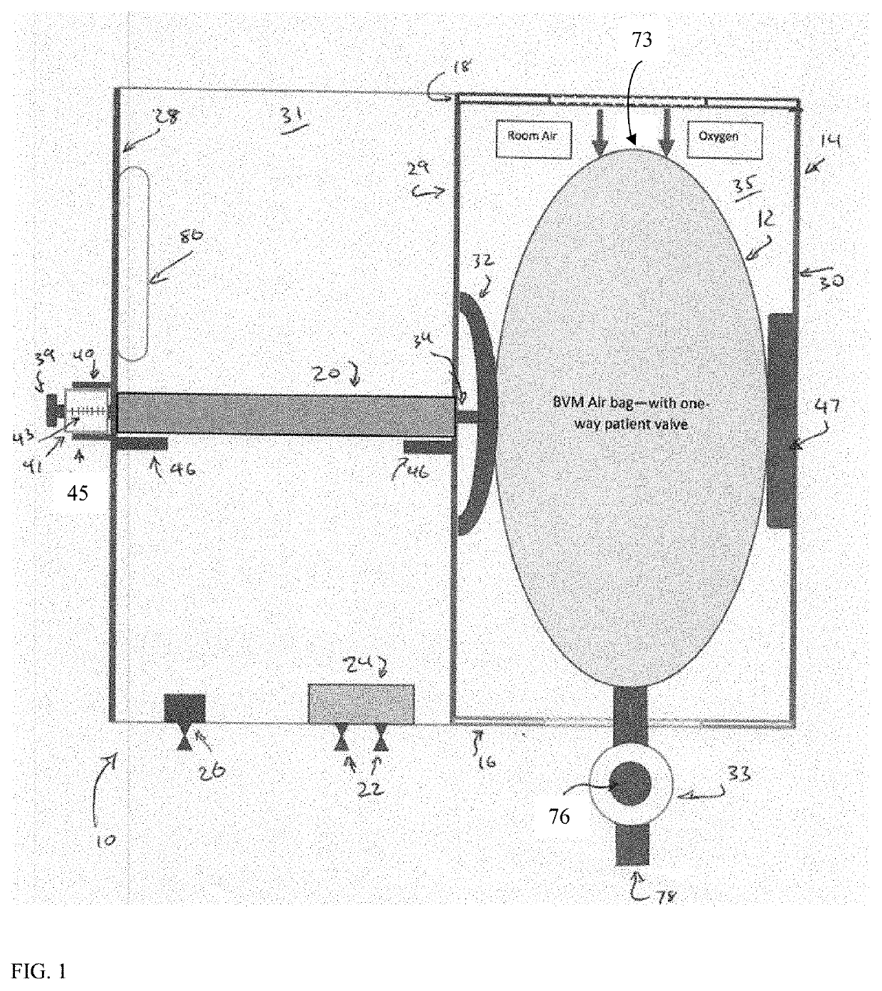
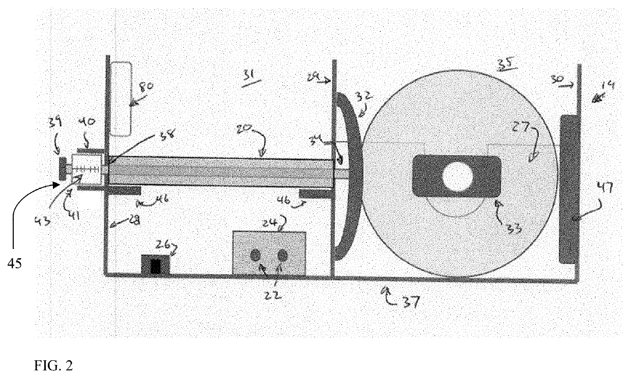
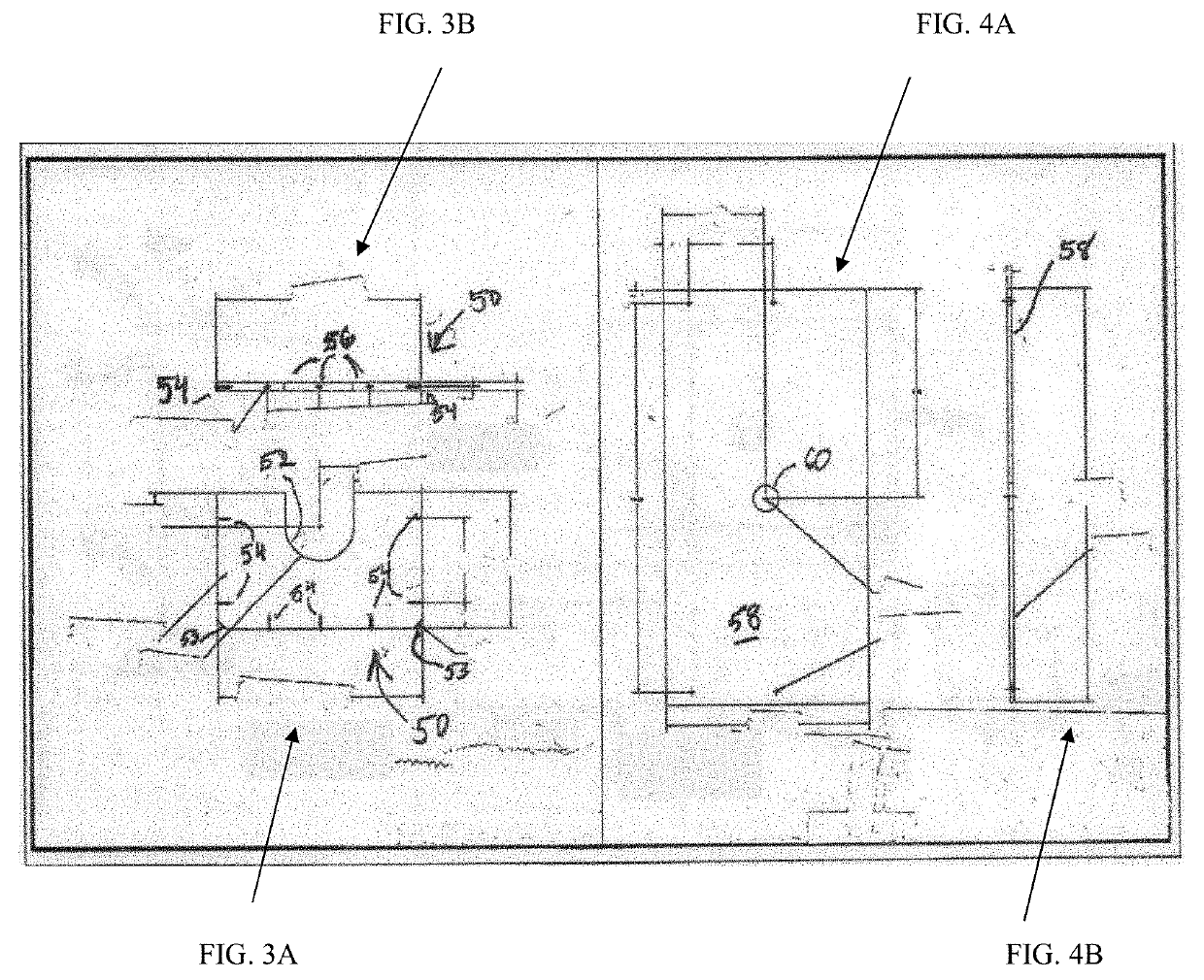
[0037]The innovation is now described with reference to the drawings, wherein like reference numerals are used to refer to like elements throughout. In the following description, for purposes of explanation, numerous specific details are set forth in order to provide a thorough understanding of the subject innovation. It may be evident, however, that the innovation can be practiced without these specific details.
[0038]While, for purposes of simplicity of explanation, the one or more methodologies shown herein are shown and described as a series of acts, it is to be understood and appreciated that the subject innovation is not limited by the order of acts, as some acts may, in accordance with the innovation, occur in a different order and/or concurrently with other acts from that shown and described herein. For example, those skilled in the art will understand and appreciate that a methodology could alternatively be represented as a series of interrelated states or events. Moreover, not all illustrated acts may be required to implement a methodology in accordance with the innovation.
[0039]Currently, some of the products described below are made by Bimba Manufacturing Co., located at University Park, Ill. Bimba is part of IMI Precision Engineering, which is a leader in motion and fluid control technologies. Many of the parts described below refer to different off-the-shelf products, whose exact characteristics can be found in publicly available catalogues and from online sources. It is to be appreciated that the below-described products are examples of components that can be used and that one of skill in the art may determine a product from a different manufacturer/producer will provide the same or substantially the same function.
[0040]As described herein, the innovation provides for a product which can be prepared inexpensively using a respiratory system which is both effective and efficient is use. In some embodiments, the device may include a respiration bag kit or bag valve mask (BVM) that may be most any size. Furthermore, the device can include an alarm to report the breakage (or failure) of a bag or an indication that a hose has come off, is loose, or otherwise dislodged. In one embodiment, the innovation can further employ use of an exhalation HEPA filter (the HEPA filter is a highly efficient, small micron particulate air filter that enables it to trap viral matter and minute bodies). In another embodiment, a PEEP (positive end-expiratory pressure) valve may be included. A PEEP valve is used, for example, where the patient is sedated and back pressure is needed to keep the lungs of the patient from collapsing. In one embodiment, the unit may be powered by compressed air for the pneumatics, with low voltage electric power used to power alarms. By design, the unit is small, lightweight and can be sold for a reasonable price. The disposable BVM respiration kits are believed to be around $20.00 (in 2020) rendering it simple and inexpensive and able to meet emergency situations.
[0041]In one aspect, the innovation provides a respirator ventilator. As described below, a respirator ventilator according to an embodiment may comprise a pair of adjacent chambers. One chamber, referred to herein as the compressor chamber, is where an air bag is disposed. In an embodiment, the air bag is secured within the compressor chamber via at least one securing component. Suitable securing components include flexible bands (e.g., elastic bands); a receiving plate configured to accommodate the air bag, and the like. In one embodiment the air bag may secured by elastic bands. The air bag may be in a horizontal position having an air or oxygen intake port at one end and an oppositely located discharge end or discharge port. A tube device patient valve may be attached to the discharge end, through which air is discharged in response to the compression of the bag, and is transmitted to the patient through the discharge port. A second chamber, referred to herein as the cylinder chamber, houses a cylinder of a piston-cylinder assembly. In one embodiment, the piston-cylinder assembly is configured to drive a piston in a reciprocating motion through an orifice in a wall separating the compression chamber from the cylinder chamber. In one embodiment, there may be a top (e.g., a metal top) and side walls on the cylinder chamber to facilitate keeping the device clean in a medical environment. In addition, or alternatively, there may be a top wall. In one embodiment, the top wall may be a metal top wall. In one embodiment, the top wall of the compressor chamber may be clear or include an area through with the compressor chamber can be viewed to allow observation of the operation. One advantage of this configuration is that it makes it possible the use of air bags from many different suppliers, regardless of dimensional differences and exhaust port configurations. In one embodiment, the cylinder drives the piston towards the air bag to compress the air bag. The piston may be provided with a dome shaped piston head, referred to herein as a pressure plate, for compressing the air bag to force air out of the air bag through the tube device to the patient. The force of the pressure plate is applied above the middle of the air bag to maintain stability of the air bag by urging it against a receiving plate mounted on the opposing wall and to the lower corners of the compression chamber. This configuration may help to prevent erratic movement of the air bag towards the upper portion of the compression chamber.
[0042]According to an embodiment, the cylinder-piston assembly may include a variable stroke piston having an adjustable effective length. In one embodiment, the effective length may be adjusted by means of a tube-within-a-tube device that operates according to a calibrated scale(s) on the inner tube. Likewise, the rate of the reciprocating movement of the piston can also be varied to control the Respiration Rate and I/E ratio. These controls enable the adjustment of the minute volume of air being transmitted to the patient where Minute Volume is the product of Tidal Volume and Respiration Rate.
[0043]In one embodiment, the respirator ventilator may be compatible with PEEP valves by means of a one way flapper valve in an inhalation breathing circuit. Breathing circuits of the nature needed for a respirator ventilator are readily available from FDA approved medical suppliers. A single limb breathing circuits of this nature are typically supplied with flexible corrugated inhalation and exhalation tubes, a patient wye or adaptor, pressure monitoring tube and an exhalation valve (e.g., CareFusion 55-001795 by Vyaire Medical). This flapper valve prevents the exhaust air from bypassing the PEEP valve. Thus, for example a pressure sensor alarm module is connected by flexible tubing to a patient wye connector pressure port, and a tee connector, (e.g., an AirLife connector (004081))—the discharge from the latter to a one-way disposable flapper valve. An example of a suitable flapper valve includes an AirLife one-way valve (001800). In one embodiment, the discharge from the latter valve leads both to the mask or intubation tube to the patient, and the exhaust air valve to a HEPA filter and PEEP valve and then to an exhaust to the room environment.
[0044]In one embodiment, the respirator ventilator may include a display for one or more functions to provide information to a medical provider and/or caretaker. For example, the display may be Respiration Rate, I/E ratio, PEEP, Inspiration Time, PIP, an air flow display and/or a tidal volume display.
[0045]In one embodiment the device includes a single limb patient circuit with an exhalation valve (e.g., CareFusion 55-001795 by Vyaire Medical). The pressure to supply this exhalation valve comes from tubing connected to a Tee placed in the patient circuit immediately downstream from the BVM. As the bag is squeezed the inhalation circuit is pressurized and the resulting pressure closes the exhalation valve ensuring delivery of the set tidal volume to the patient. When the pressure drops at the end of the BVM compression stroke the exhalation valve opens allowing the lungs to expire air through the PEEP valve and filter into the room atmosphere. This simple pneumatic piping eliminates the need for complex pumps and electric valves to control the patient exhalation valve.
[0046]According to an aspect, the respirator ventilator may be pneumatically powered/controlled, electrically powered/controlled, or both. As described above, the piston assembly may be pneumatically controlled. In one embodiment, the piston assembly may be controlled electrically, either as a back-up in case of failure of the pneumatic control or solely electrically-controlled. In one embodiment, other features of the respirator ventilator may be electrically controlled (e.g., the display(s) and alarm(s) while the piston assembly is pneumatically controlled. In one embodiment, a battery may provide energy to the unit.
[0047]Turning now to FIG. 1, FIG. 1 shows in schematic form a respirator ventilator 10 according to an embodiment of the innovation. Respirator ventilator 10 incorporates a self-inflating air bag 12 that is disposable. Self-inflating air bag 12 is incorporated in a housing 14. In the embodiment depicted in FIG. 1, housing 14 is shown as including three parallel walls. The walls may comprise sufficiently rigid material appropriate for medical device use. In one embodiment, the material may be a stainless steel plate (e.g., a 304 stainless steel plate). In the embodiment depicted in FIG. 1, the housing 14 has at its base a stainless BVM cradle plate 16 that has notches where the BVM bag is placed. In one embodiment, the dimensions of the cradle plate may have dimensions of 4″ by 6″. In one embodiment, plate 16 is a 1/16″ 304 stainless plate. In one embodiment, the respirator ventilator 10 may include a receiving plate 47. The receiving plate 47 is configured to secure the BVM bag and facilitate compression of the BVM bag. The top of housing 14 is held in place by fasteners 18. In one embodiment, the fasteners 18 may be SS button head hex fasteners. Self-inflating air bag 12 is compressed by means of a cylinder. FIG. 1 further includes a front and rear mount double ended air cylinder 20. A suitable stroke double ended cylinder includes a double ended 3″ stroke front and rear mount 9/16 bore cylinder (e.g., a Bimba 023DE-20). Operation of the front and rear mount double ended air cylinder 20 is controlled by two flow control valves 22 (e.g., Bimba FQPS2K). The latter controls a valve 24, such as a 4 way 5 port air pilot valve (e.g., Bimba M4A22006). Part of the control of the stroke double ended air cylinder 20 is controlled by means of a 3 port manual toggle (e.g., Bimba MV35), indicated by numerical indicator 26 in FIG. 1. It is to be understood and appreciated that while Bimba parts are described for use herein, other equivalent off-the-shelf parts can be employed without departing from the spirit and scope of this innovation and claims appended hereto. Further, it is to be understood and appreciated that the embodiments and aspects described herein are described using parts provided by specific manufacturers/distributors (e.g., Bimba). While these parts have been shown to be adequate for use, other equivalent or alternate off-the-shelf components can be employed and are to be included within the scope of this specification and claims appended hereto.
[0048]With continued reference to FIG. 1, air and oxygen are fed into one end of BVM bag 12 via inlet port 73 (see FIG. 9), and upon the compression applied to self-inflating (and disposable) BVM bag by pressure plate 32, air and oxygen are forced through a BVM one-way patient valve 33 to the patient. Domed pressure plate 32 is urged against BVM bag 12 by means of the linear motion of piston 38 (see FIG. 2) moving in front and rear mount double ended cylinder 20. Locking knob 39 is part of a “tube-in-tube” calibration device 45 (see FIG. 8) for adjusting the stroke of piston rod 34, on which a scale 43 is shown for making an exact setting.
[0049]FIG. 2 is a side view of respirator ventilator 10 according to an embodiment of the innovation. FIG. 2 shows self-inflating air BVM bag 12 as being mounted on holding device 27. The front and rear mount double ended cylinder 20 is operationally attached to domed compression plate 32 which is moved in a reciprocal linear motion by means of a piston rod 34 extending an end of the front and rear mount double ended air cylinder 20, and a piston rod 38 extending to the other end of the front and rear mount double ended air cylinder 20. In one embodiment, the tidal air volume may be adjustable. Still referring to FIG. 2, the respirator ventilator 10 may include a locking knob 39 and threaded within adjustable graduated inner cylinder tube 41, as described above, and marked for tidal volume, and outer cylinder tube 40. (See FIG. 8.)
[0050]Continuing with FIG. 2, housing 14 includes three parallel plates forming two chambers. Plates 28 and 29 form a first chamber 31, and plates 29 and 30 form a second chamber or compression chamber 35. In one embodiment, plate29 may comprise a stainless-steel plate (e.g., a 304 stainless steel plate). In one embodiment, plate 29 may have dimensions of 6″ by 12″. It is to be appreciated that the dimensions of plate 29 can be adjusted to accommodate different needs without deviating from the scope of the innovation. In one embodiment, stainless plates 28 and 30 may be each 1/16″ thick, made of 304 stainless steel and have dimensions 4″ by 6″. The latter may be bent into a U-shape with a 12″ base 37. Plate 29 may be a 12″ by 6″ plate that is ⅛″ thick and holds front and rear mount double ended cylinder 20. Referring to FIG. 1, fasteners 18 (e.g., SS button head hex fasteners) are 1/16″ SS button heads.
[0051]Still referring to FIG. 1, a four way five port pilot valve 24 is configured to change the direction of movement of piston rods 34 and 38 (see FIG. 2), and domed compression plate 32. In one embodiment, three port toggle switch 26 is an air on/off switch 26 that may be included. In an embodiment, the air on/off switch may be a three port manual detent toggle.
[0052]If needed in aspects, adapters may be provided to accommodate different sized tubing or piping (e.g., pneumatic pipe or flexible tubing. Suitable examples of adapters may include: two adaptors for 10-33 to 1/8 NPT (e.g., model D/855/A) and two PTC T-fittings such as two ports 1/4 and one port 5/32 (e.g., model C20630402-618).
[0053]In one embodiment, two stroke completion sensors 46 may be provided to reverse directions of the air cylinder. In an example, the sensors 46 can be Bimba model SCD-112. Alternatively, this can be accomplished through manual three-way pneumatic contact valves or electric switches that are depressed by the compression plate and tube-in-tube mechanism. There are alternatively a number of pneumatic switches, pressure switches, magnetic and proximity sensors that can detect the end of the set stroke. The electric switches can control an air solenoid to reverse the stroke.
[0054]Also provided are two flow controls 22 with an adjustment knob and locking nut. In one embodiment, Bimba model number FQPS2K may be used for controlling speed.
[0055]In one embodiment, a 1/8 NPT-1/4 OD tube straight may be provided as connectors (e.g., model number C24250218-618). A 1/8 NPT-5/32 OD tube straight as a connector may further be provided, (e.g., model number C2450418-618). Further included may be a 1/8 NPT-1/4 OD tube 90 degree as connectors, (e.g., model number C24470218-618). An 1/8 NPT-5/32 OD tube 90 degree as connectors may also be included, (e.g., model number C24470418-618). The final part of the tubing may include a 5/16″ PE tubing, a ⅛″ PE tubing and a compressed air inlet male bayonets fitting ¼″ NPT from various suppliers to adapt to dry medical compressed air supply. Hospitals use their own hoses for wall plates, and there are many different sizes used in hospitals in the United States.
[0056]Details of embodiments of the housing portion of respirator ventilator 10 according to an aspect of the innovation are shown in FIGS. 3-7, which depict an example according to an embodiment of the innovation. Referring first to FIG. 3A, a side plate 50 is shown. Side view of a side plate 50 indicates that side plate 50 may be formed as a rectangle with a U-shaped cut-out 52 formed therein to house a BVM bag. The U-shaped cut-out 52 helps put the BVM in position in the compressor chamber because the BVM should not be locked in the slot. In one embodiment, there may be two corner cut-outs 53 on the lower portion of side plate 50. U-shaped cut-out 52 is provided to form a resting place for holding device 27 shown in FIG. 2 of the BVM air bag 12. In an embodiment, a pair of elastic bands may be secured on eyebolts mounted on base plate 37. These bands may be configured to loop around the ends of the BVM and attach to open hooks on the top of the back wall. In one embodiment, a machined polyamide (e.g., Delrin®) receiving plate 47 is attached to the back wall to aid in holding the BVM during compression.
[0057]In one embodiment, a series of head screws 54 may be included on 3 sides of side plate 50. Screw holes 56 are provided at the end of side plate 50 as shown in FIG. 3B.
[0058]A cross plate 58 is shown in FIGS. 4A and 4B. FIG. 4A is a plan view of cross plate 58. Cross plate 58 includes an aperture 60.
[0059]Referring to FIGS. 5A-5D, a support frame 62 is shown for an embodiment according to the innovation. FIG. 5A is a plan view, FIG. 5C is an end view and FIGS. 5B and 5D are side views.
[0060]FIGS. 6A-6B depict an embodiment according to an aspect of the innovation and shows the cover for support frame 62. FIG. 6 shows a cover 64, with FIG. 6A being a plan view and FIG. 6B being an end view. FIG. 6A shows that cover 64 has a rectangular cross section with a U-shaped handle 66. Emergency respirator ventilator 10 is portable and can be carried by means of handle 66 when it is closes support frame 62.
[0061]FIGS. 7A-7C depiction overall assembly for respirator ventilator 10 according to an embodiment. FIG. 7A is a side view of the emergency respirator ventilator 10. FIG. 7B is a plan view of respirator ventilator 10. FIG. 7C is a side view of respirator ventilator 10. Support frame 62 is shown in FIG. 7C. Side plate 50 is illustrated in FIG. 7B. FIG. 7A shows cross plate 58. Also shown in FIG. 7A is cover 64. A front and rear mount double ended air cylinder 20 (e.g., Bimba 3″ stroke) is depicted in FIG. 7B. Also shown in FIG. 7B is a four way five port air pilot valve 24 and three way three port manual toggle 26. Threaded stud bumpers 68 may be further provided. A pair of stainless button head screws 70 and hex nuts 72 through screws 70 extend are shown in FIG. 7A.
[0062]According to an aspect, the respirator ventilator may provide an adjustable tidal volume to a patient. The tidal volume may be adjusted by, for example, adjusting the stroke of the piston/piston assembly. This in turn allows for a different rate of compression of the compressible air bag. Once selected, the respirator ventilator supplies a constant tidal volume to the patient by applying a consistent pressure to the compressible air bag. FIG. 8 depicts an embodiment of a “tube-in-tube” calibration device 45 for adjusting the stroke of piston rod 34. The calibration device 45 may include an outer cylinder/tube 40 and an inner cylinder/tube 41. The inner cylinder/tube 41 may be configured to slidably fit within the outer cylinder tube 40. The inner cylinder 41 may be a graduated, adjustable inner tube having markings corresponding to tidal volume 43. Locking cap 39 locks the adjustable inner tube 41 in place once the desired tidal volume is selected. It will be appreciated that other means for adjusting the stroke of the piston or for adjusting the tidal volume may be used. For example, magnetic sensors, stroke completion sensors and/or proximity sensors may be used. These embodiments are to be included within the scope of the innovation described as well as the claims appended hereto.
[0063]Turning next to FIG. 9, self-inflating air bag 12 comprises an intake end with an inlet port 73, and outlet port 74 with a patient valve device 33 and tube 76 for providing an access to the patient's mouth to receive air, oxygen or a combination of air and oxygen as required. A tube 78 is also shown for receiving waste gas from the patient (not used in this resuscitator ventilator device).
[0064]Respirator ventilator 10 is very effective as an emergency device. In some embodiments, it only incorporates one moving part, namely integral piston rod 34-domed pressure plate 32 for squeezing self-inflating air bag 12 in order to provide oxygen to a patient. In one embodiment, the unit is very portable, weighing less than about twenty pounds (a unit according to an embodiment of the innovation may be about fifteen pounds). In one embodiment, the unit has approximately a 12″×12″ footprint. In the aspect described above, it is operated by compressed air. Low voltage electric power provides current for the display, solenoids, and the alarms. It is to be appreciated that electrically powered units can be employed in a similar manner as those described supra with regard to pneumatic embodiments. These electrically-powered embodiments are to be included within the scope of the innovation described as well as the claims appended hereto. In operation, the unit can provide at least thirty-five breaths per minute, which is-higher than the standard requirement or performance metrics of conventional systems. Today, it is believed that this unit could be very affordable. Its cost is based on the purchase price and the operating costs would be much less expensive than not only multi-modal ventilators, but also simpler ventilators presently available. Currently used ventilators have operating costs higher than those according to an embodiment of the innovation because the currently available “low cost” gas driven ventilators use high volumes of more expensive medical grade oxygen.
[0065]As indicated above, in some embodiments an alarm system may be included. An alarm may be activated when a BVM bag breaks, when the BVM bag is disconnected, when high pressure occurs (such as in the event that the patient is unconscious or sedated), in the event a tube is blocked or a tube is kinked, and when the patient's lungs become inelastic and it is necessary to maintain a-higher pressure. According to an aspect, an embodiment of the innovation may include an appropriate alarm system.
[0066]In one embodiment, the unit may include a display unit. The display unit may display PIP, PEEP, Respiration Rate, I/E ratio, Inspiration Time, and alarms, measurements of appropriate pressure readings, improper tube connections etc. In one embodiment, the display may include an alarm reset button. In one embodiment, the reset button is manually operated.
[0067]Referring to FIG. 10, a pressure monitoring sensor 80 is disposed in the cylinder chamber. A tube 87 connects the sensor module to a pressure port in the patient circuit near the patient's mouth. An exhalation/exhaust valve 82 including an exhalation valve tube 85 leading thereto is operatively connected to a tee 89 that feeds pressure through a small tube 85 to the exhaust valve 82. This provides simple and reliable control to close the exhalation valve during inhalation ensuring the prescribed tidal volume of air is delivered to the patient. Once compression of the compressible air bag 12 is complete, the pressure provided by this configuration ceases, allowing for exhalation. Also attached to the tee 89 is a disposable one-way flapper valve 81 for blocking the exhaust from exiting the patient valve tube 78 to enable PEEP. This allows the use of multiple configurations of BVMs that may have different exhaust port systems. One-way flapper valve 81 is connected by the single limb breathing circuit to a wye 90 at the patient. The exhaust tube from the wye is connected to the exhaust valve 82, the adjustable PEEP valve 88 and the HEPA filter 86 where exhaust exits to the room. This configuration provides the ability to adjust air supply (e.g., respiration rate, tidal volume, and I/E ratio) for a patient through the control of the air cylinder 20 via adjustment of the flow control valves 22 and the tube in tube assembly 45.
[0068]Turning to FIG. 11, a manikin 92 in the form of a human is shown having air inlet tube 84 being received in the mouth of manikin 92.
[0069]The innovation has been described in detail, and those familiar with the art will be able to understand the relevant elements of the device disclosed herein, with reference to the description set forth above and from the appended claims.

PUM

no PUM

Description & Claims & Application Information

We can also present the details of the Description, Claims and Application information to help users get a comprehensive understanding of the technical details of the patent, such as background art, summary of invention, brief description of drawings, description of embodiments, and other original content. On the other hand, users can also determine the specific scope of protection of the technology through the list of claims; as well as understand the changes in the life cycle of the technology with the presentation of the patent timeline. Login to view more.

Similar technology patents

Air-curtain device

InactiveUS20150241075A1effective
Owner:THERMOSCREENS

Application of pleurotus ferulae polysaccharide in preparation of dog zona pellucida 3DNA vaccine adjuvant

ActiveCN107158373AEffectivegood immunogenicity
Owner:XINJIANG UNIVERSITY

Liver-protecting drinks for diet and health regimen

InactiveCN102258755AEffectivestrong aroma
Owner:凌一峰 +1

Classification and recommendation of technical efficacy words

  • efficient in operation
  • effective

Selected processing for non-equilibrium light alloys and products

InactiveUS20030183306A1high valueeffective
Owner:HEHMANN FRANZ

Detergent dispenser for a washing machine

ActiveUS20050188730A1effective
Owner:WHIRLPOOL CORP

Surface-coated pearlescent pigments, process for preparing them, and their use

InactiveUS20070032574A1good processing propertyeffective
Owner:ECKART GMBH & CO KG

Soluble microneedle arrays for buccal delivery of vaccines

InactiveUS20150112250A1easy administrationeffective
Owner:THERAJECT INC.

Inhibition of corrosion in fluid systems

ActiveUS20050025661A1effectiveeffective corrosion control
Owner:BL TECH INC
Why Eureka
Try Eureka