Image processing method, apparatus, program, and image forming apparatus

a technology of image processing and forming apparatus, applied in the direction of digital output to print units, power drive mechanisms, instruments, etc., can solve the problems of non-jetting that cannot be corrected with high quality, streaks that cannot be appropriately corrected, and artifacts, etc., to achieve high-quality images.

Pending Publication Date: 2021-11-04
FUJIFILM CORP
View PDF3 Cites 7 Cited by
  • Summary
  • Abstract
  • Description
  • Claims
  • Application Information

AI Technical Summary

Benefits of technology

[0014]The present invention is conceived in view of such a matter and resolves at least one of a plurality of problems above, and an object thereof is to provide an image processing method, an apparatus, a program, and an image forming apparatus capable of suppressing an artifact in a boundary part of a threshold value matrix in a case of performing quantization using the threshold value matrix, and performing high-quality correction without deterioration in granularity of a correction portion even in a case where defective recording elements occur in a concentrated manner.
[0016]According to this aspect, by applying the third threshold value matrix to a boundary portion between the first threshold value matrix and the second threshold value matrix, an artifact in the boundary portion can be suppressed.
[0018]According to this aspect, in a case where the defective recording elements are concentrated, high-quality correction can be performed without deterioration in granularity of a correction region including the second image region.
[0026]According to this aspect, a boundary between the first threshold value matrix and the second threshold value matrix can be smoothly connected by suppressing the artifact.
[0039]According to the present invention, in a case of performing the quantization on the image data using the threshold value matrix, the artifact in the boundary part of the threshold value matrix can be suppressed, and a high-quality image can be obtained.

Problems solved by technology

Generally, in a case of switching the sub-matrix to be used depending on regions of the image, a problem arises in that an artifact occurs in a boundary portion.
However, in this method, the non-jetting cannot be corrected with high quality in a case where the non-jetting occurs in a concentrated manner.
Thus, granularity of the corresponding region deteriorates, and a problem arises in that the streak is not appropriately corrected.
In the technology of JP4670696B, since the artifact in the boundary portion between the plurality of sub-matrices cannot be considered for the sub-matrices, a problem arises in that correction cannot be clearly performed.

Method used


Image

  • Image processing method, apparatus, program, and image forming apparatus
  • Image processing method, apparatus, program, and image forming apparatus
  • Image processing method, apparatus, program, and image forming apparatus

Examples


first example

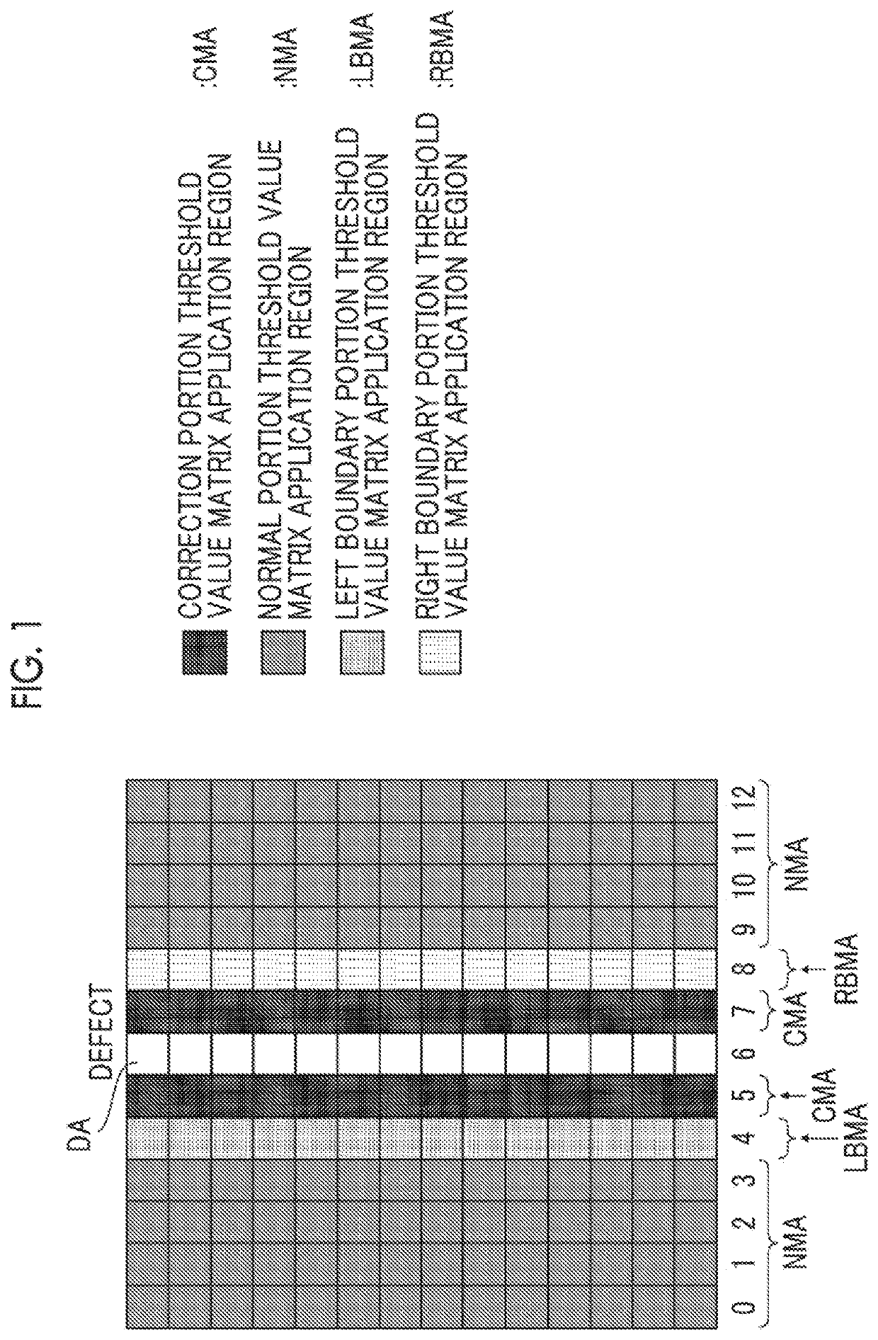
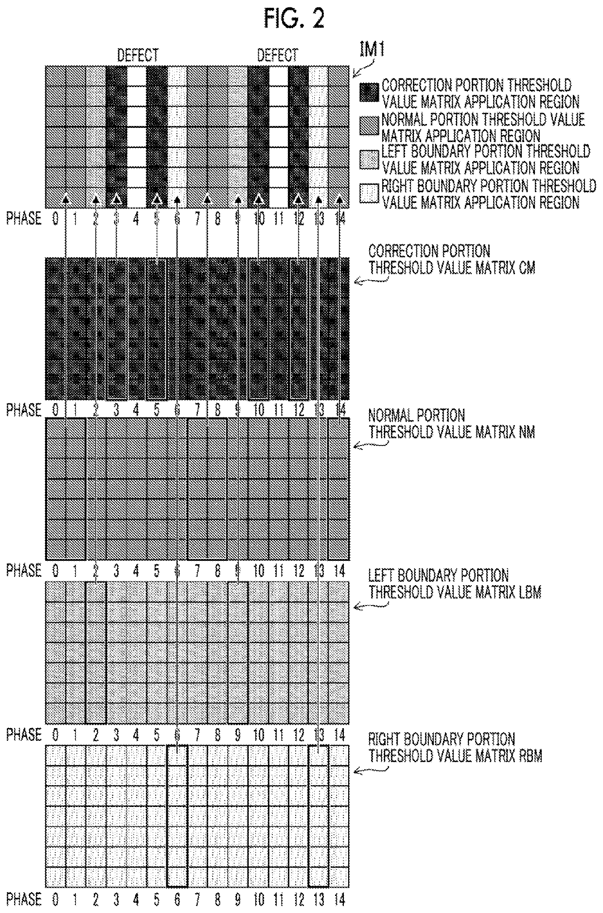
[0081]FIG. 2 is a conceptual diagram illustrating a summary of quantization processing according to a first example. As illustrated in FIG. 2, image values are quantized by selectively referring to each threshold value matrix in the threshold value matrix set in accordance with the address of the image.

[0082]In FIG. 2, an example of an image IM1 of which the number of pixels is 8 rows x 15 columns is illustrated. In a case of FIG. 2, the fourth column and the eleventh column are the defective portions DA corresponding to the defective nozzles within a range of the leftmost zeroth column to a rightmost fourteenth column.

[0083]As illustrated in FIG. 2, a phase coordinate of the corresponding threshold value matrix is referred to in accordance with the address of the image. The first example illustrated in FIG. 2 is an example in which a phase of the address of the image matches a phase of the threshold value matrix to be referred to. That is, for example, a threshold value correspondi...

second example

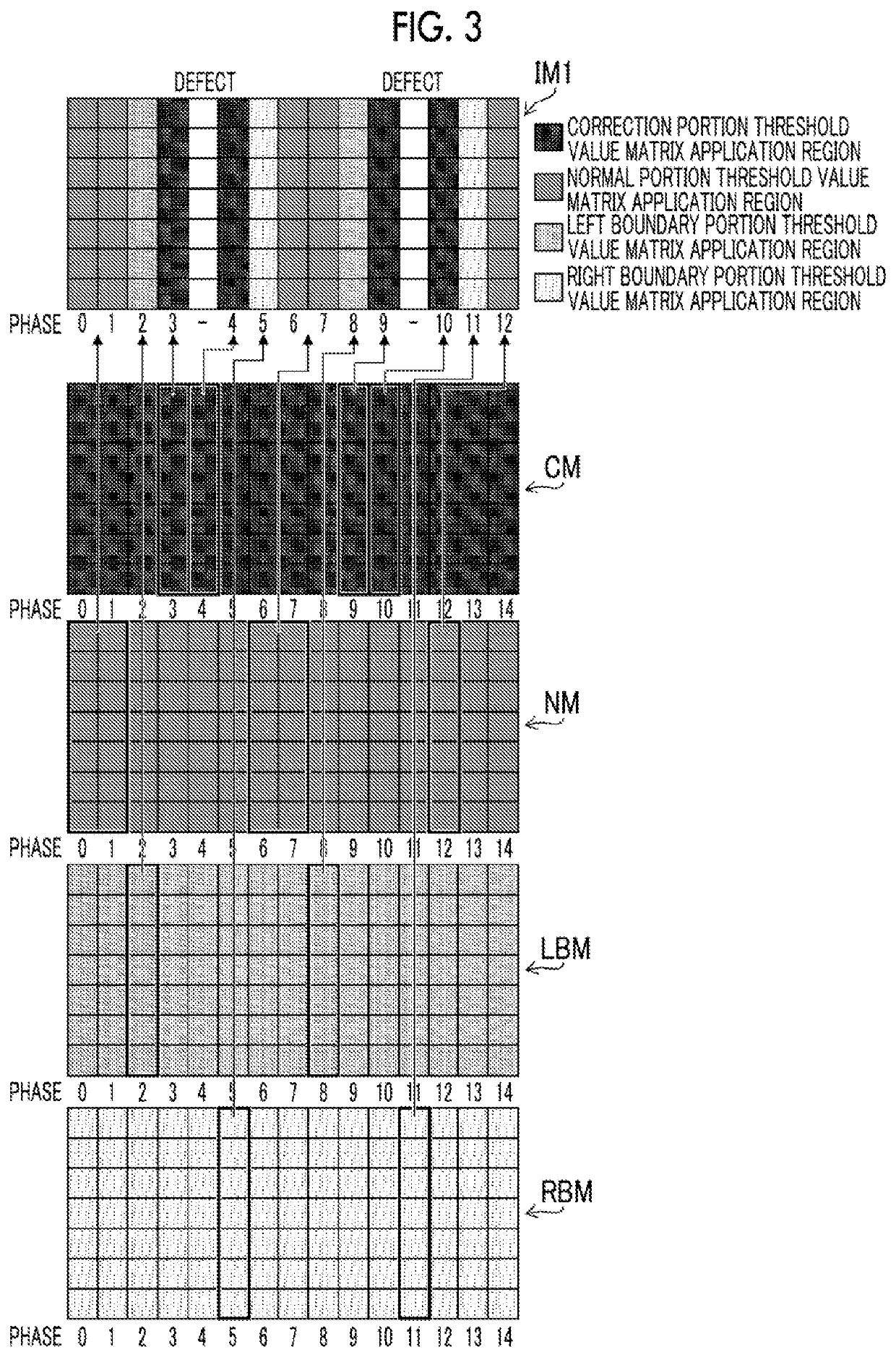
[0085]FIG. 3 is a conceptual diagram illustrating a summary of quantization processing according to the second example. In the second example illustrated in FIG. 3, the phase coordinate of the threshold value matrix corresponding to the address of the image is referred to in the same manner as the first example. However, in the defective portions DA of the image, it is configured that the phase of the position to be referred to is offset (shifted). A method of offsetting a phase of a reference position of the threshold value matrix in such a manner is a method disclosed in JP5791155B. By doing so, the threshold value matrix can be continuously referred to even in defective nozzle portions. Thus, occurrence of artifacts in not only the boundary portion but also the correction portion can be suppressed.

Example of Processing Flow

[0086]FIG. 4 is a flowchart illustrating an example of a processing content based on the image processing method according to the embodiment of the present inv...


PUM


Abstract

An image processing method, an apparatus, a program, and an image forming apparatus capable of suppressing an artifact in a boundary part of a threshold value matrix and performing high-quality correction even in a case where defective recording elements are concentrated are provided. An image processing method according to an aspect of the present invention includes performing correction of suppressing visibility of an image defect using recording elements around a defective recording element of a recording head by disabling the defective recording element, and performing quantization of data of an image, in which processing of the quantization includes applying a first threshold value matrix to a first image region that is separated by more than a first distance from a defective image region, applying a second threshold value matrix to a second image region separated by less than the first distance, and applying a third threshold value matrix to a third image region at a boundary between the first image region and the second image region.

Description

CROSS-REFERENCE TO RELATED APPLICATIONS[0001]The present application is a Continuation of PCT International Application No. PCT / JP2020 / 008730 filed on Mar. 2, 2020 claiming priority under 35 U.S.0 §119(a) to Japanese Patent Application No. 2019-040663 filed on Mar. 6, 2019. Each of the above applications is hereby expressly incorporated by reference, in its entirety, into the present application.BACKGROUND OF THE INVENTION1. Field of the Invention[0002]The present invention relates to an image processing method, an apparatus, a program, and an image forming apparatus and particularly, to a halftone processing technology for performing gradation representation by recording dots in digital printing of an ink jet printing apparatus or the like, and a correction technology for decreasing visibility of an image defect caused by a defect of a recording element.2. Description of the Related Art[0003]In an ink jet printing apparatus of a single pass method that is a form of an image forming...

Claims


Application Information

Patent Timeline
Patent Type & Authority Applications(United States)
IPC IPC(8): B41J2/045G06F3/12
CPCB41J2/0451G06F3/1211B41J2/04581G06F3/1234B41J2/04508G06F3/121B41J2/2146B41J2/2139B41J2025/008G06F3/1208G06F3/1247H04N1/405H04N1/4015
Inventor SHIBATA, HIROYUKI
Owner FUJIFILM CORP
Why Eureka
Try Eureka