Frame interpolation apparatus and method

a frame interpolation and frame technology, applied in the direction of picture reproducers using projection devices, signal generators with optical-mechanical scanning, television systems, etc., can solve the problems of blurred edges of moving objects in images, blurred edges of moving objects, blurred edges or jerky motion, etc., and achieve accurate motion vectors from image information alone.

Inactive Publication Date: 2012-06-21
MITSUBISHI ELECTRIC CORP
View PDF1 Cites 18 Cited by
  • Summary
  • Abstract
  • Description
  • Claims
  • Application Information

AI Technical Summary

Benefits of technology

[0013]Image degradation is estimated and corrected in the present invention on the basis of the motion vector distribution. I...

Problems solved by technology

A resulting problem is that the edges of moving objects in the image appear blurred, because while the human eye follows the moving object, its displayed position moves in discrete steps.
A related problem, referred to as judder, occurs when a television signal is created by conversion of a video sequence with a different frame rate, or a video sequence on which computer processing has been performed, because the same image is displayed continuously over two or more frames, causing motion to be blurred or jerky.
It is difficult, however, to derive accurate motion vectors from image information alone.
When the estimated motion vectors represent actual motion incorrectly, the interpolated frame generated from the motion vectors is marred by image defects.
In conventional frame interpolation methods such as the one described in J...

Method used


Image

  • Frame interpolation apparatus and method
  • Frame interpolation apparatus and method
  • Frame interpolation apparatus and method

Examples


first embodiment

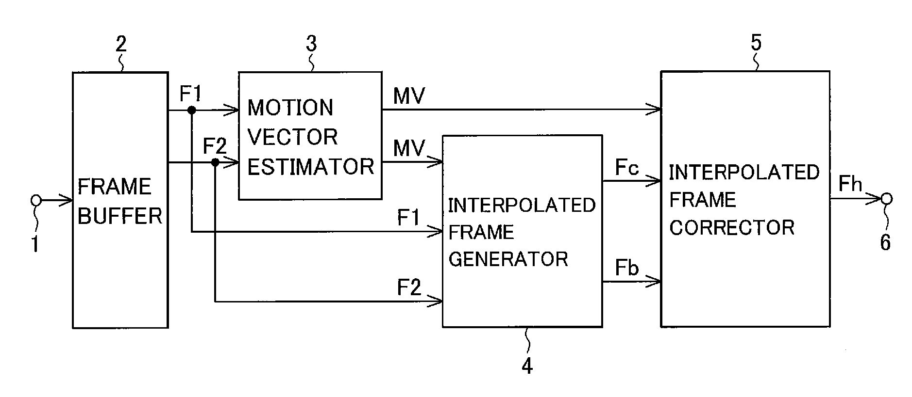
[0030]Referring to FIG. 1, the frame interpolation apparatus in the first embodiment includes a video input terminal 1, a frame buffer 2, a motion vector estimator 3, an interpolated frame generator 4, an interpolated frame corrector 5, and an interpolated frame output terminal 6.

[0031]A video signal input from the video input terminal 1 is stored in the frame buffer 2.

[0032]The motion vector estimator 3 receives first frame data F1 and second frame data F2 from the frame buffer 2 and outputs motion vectors MV. In the following description, the term “frame” may also be used to mean “frame data”. The first frame F1 is the latest (current) frame; the second frame F2 is the frame immediately preceding the first frame F1.

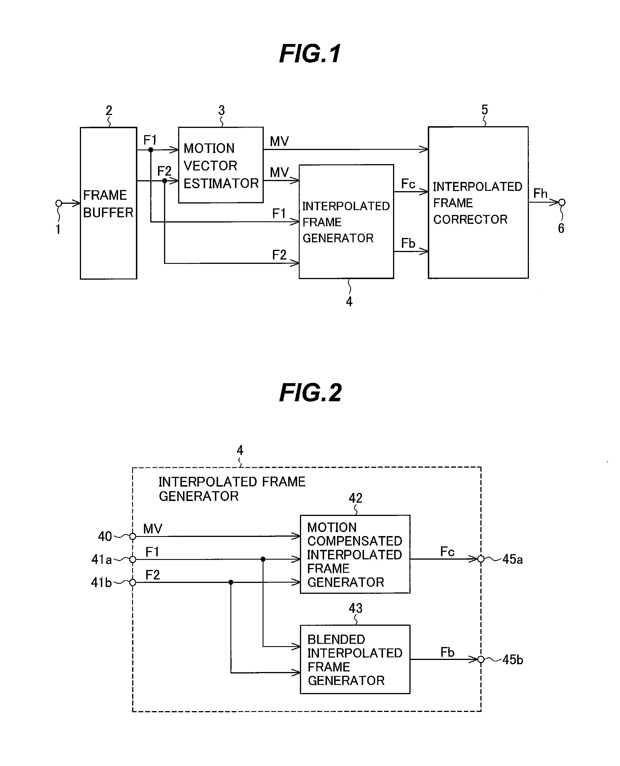
[0033]The interpolated frame generator 4 receives motion vectors MV from the motion vector estimator 3 and the first and second frames F1 and F2 read from the frame buffer 2, outputs a motion compensated interpolated frame Fc generated taking image motion into considera...

second embodiment

[0124]A second embodiment of the invention will now be described.

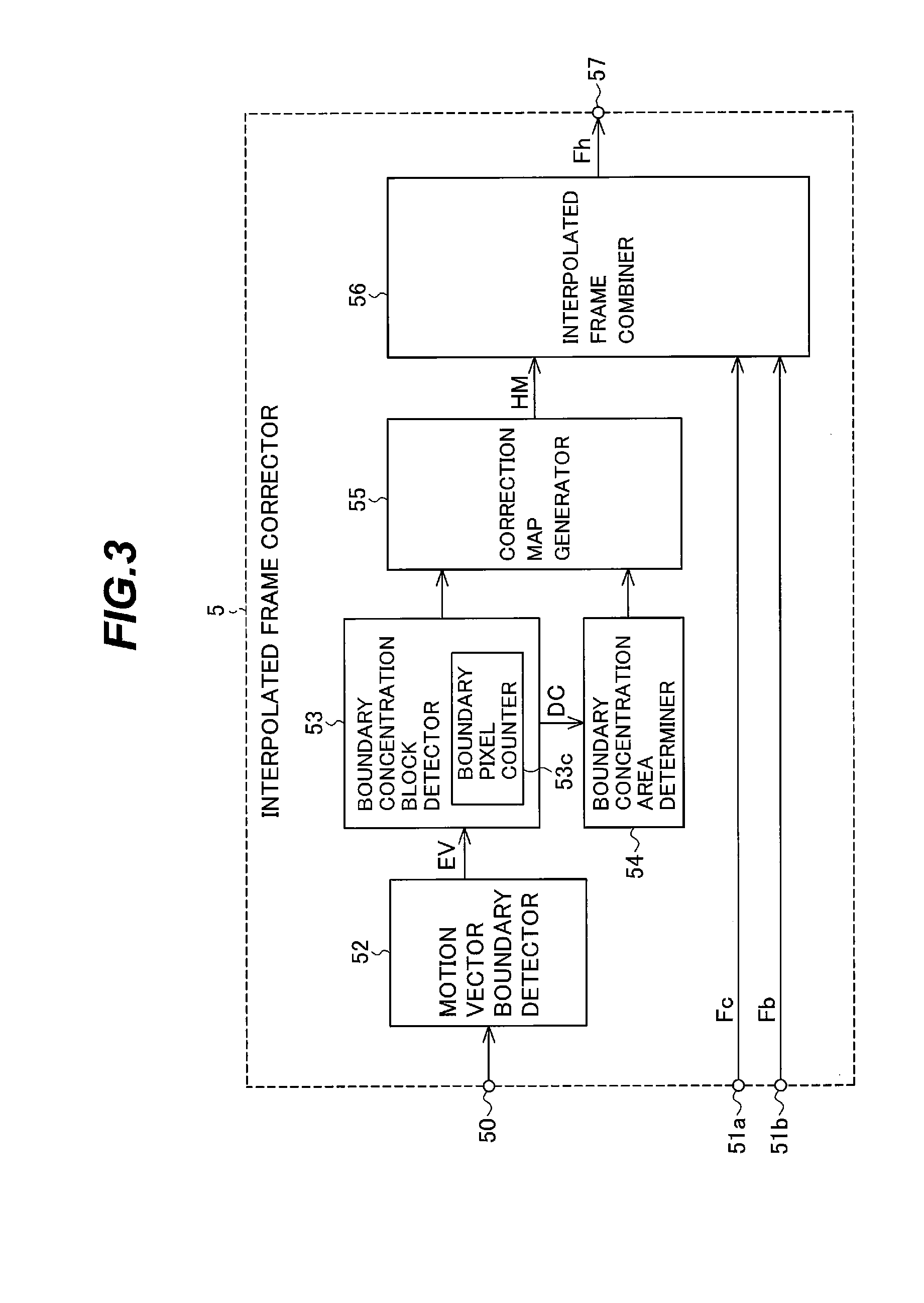
[0125]The general structure of the frame interpolation apparatus in the second embodiment is the same as shown in FIG. 1, but the internal structure of the interpolated frame corrector 5 is different. The boundary concentration area determiner 54 in the interpolated frame corrector 5 shown in FIG. 3 is replaced in the second embodiment by the different boundary concentration area determiner 58 shown in FIG. 15.

[0126]The boundary concentration area determiner 54 in FIG. 3 finds the geometric center of each block, but the boundary concentration area determiner 58 sets the gravimetric center Cw of each block as the center Cs of the corresponding boundary concentration area.

[0127]The gravimetric center Cw of each boundary concentration block Be is located within the block and is found by considering each pixel value of the block in the motion vector boundary image EV as a weight. The coordinates (xcw(Bi), ycw(Bi)) of the g...


PUM


Abstract

To interpolate a frame between a first frame and a second frame in a video signal, a motion-compensated interpolated frame is generated and then corrected responsive to detection of a motion vector boundary. Positions at which an absolute value of a first or second derivative of the motion vectors is not less than a predetermined amount are found to be at a motion vector boundary, and the pixel values of the pixels in an area where boundary pixels are concentrated are corrected. Blocks with at least a predetermined proportion of boundary pixels are found to be in an area where boundary pixels are concentrated.

Description

1. FIELD OF THE INVENTION[0001]The present invention relates to a frame interpolation apparatus and method for smoothing motion in a video image by interpolating additional frames into the video signal. The invention also relates to a program used to implement the frame interpolation method and a recording medium in which the program is stored.2. DESCRIPTION OF THE RELATED ART[0002]Liquid crystal television sets and other image display apparatus of the hold type continue to display the same image for one frame period. A resulting problem is that the edges of moving objects in the image appear blurred, because while the human eye follows the moving object, its displayed position moves in discrete steps. A possible countermeasure is to smooth out the motion of the object by interpolating frames, thereby increasing the number of displayed frames, so that the displayed positions of the object change in smaller discrete steps as they track the motion of the object.[0003]A related problem...

Claims


Application Information

Patent Timeline
IPC IPC(8): H04N7/01
CPCH04N7/014H04N5/145
Inventor NASU, OSAMUONO, YOSHIKIKUBO, TOSHIAKIFUJIYAMA, NAOYUKIHORIBE, TOMOATSU
Owner MITSUBISHI ELECTRIC CORP
Why Eureka
Try Eureka