
Bicycle transmission device

a transmission device and bicycle technology, applied in the field of bicycles, can solve the problems of user user's inability to carry out a single step, etc., and achieve the effect of easy detachment and maintenance, high security and strength

Active Publication Date: 2021-11-04
TIEN HSIN INDS
View PDF3 Cites 1 Cited by
  • Summary
  • Abstract
  • Description
  • Claims
  • Application Information

AI Technical Summary

Benefits of technology

The present disclosure provides a bicycle transmission device that improves upon the prior art. The device has high security, strength, and is easily detachable and maintainable. The force transmission pathway avoids the risk of stripped screw threads, making the device less prone to damage or become loose. The structures are easy to detach, assemble, and repair.

Problems solved by technology

However, said turning force is transmitted through the matching screw threads between the adapter and the connecting member, therefore, if a user applies an excessive pedaling force instantly (e.g., when out-of-saddle sprinting for climbing a hill), the screw threads could be stripped, which may cause wheel slip, making the user take an infirm step and putting the user at risk.
Therefore, the assembly process is more complicated and difficult.
However, the small sprocket is fixed to the big sprocket only through the small bolt in said Patent Publication No. 2019 / 0054765; in practice, during riding the bicycle, continuous vibration would be generated.
In such case, after a period of riding or high strength riding, the small bolt could be loosed due to continual vibration or the shear force, which brings security concerns.

Method used


Image

  • Bicycle transmission device
  • Bicycle transmission device
  • Bicycle transmission device

Examples


Embodiment Construction

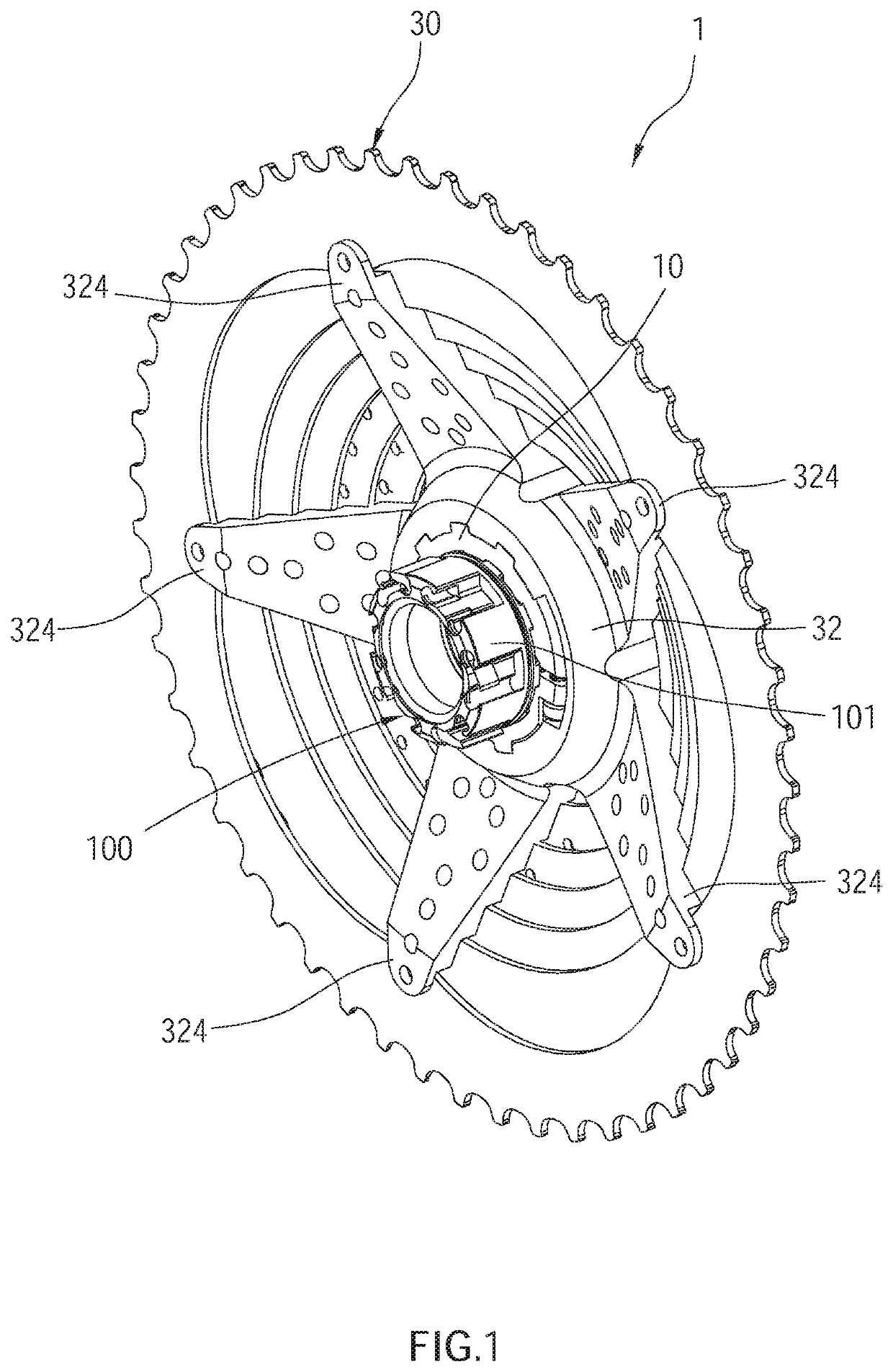
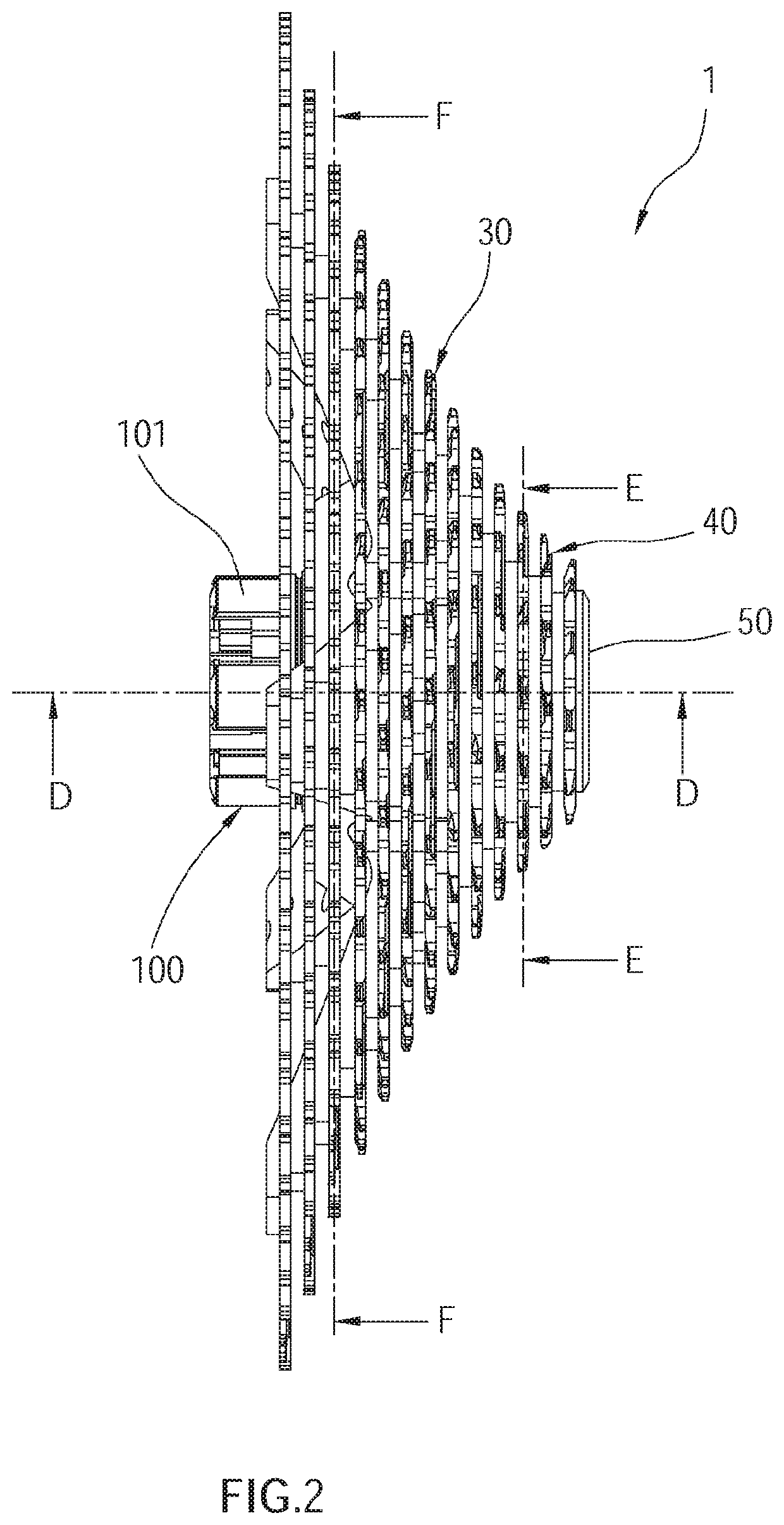
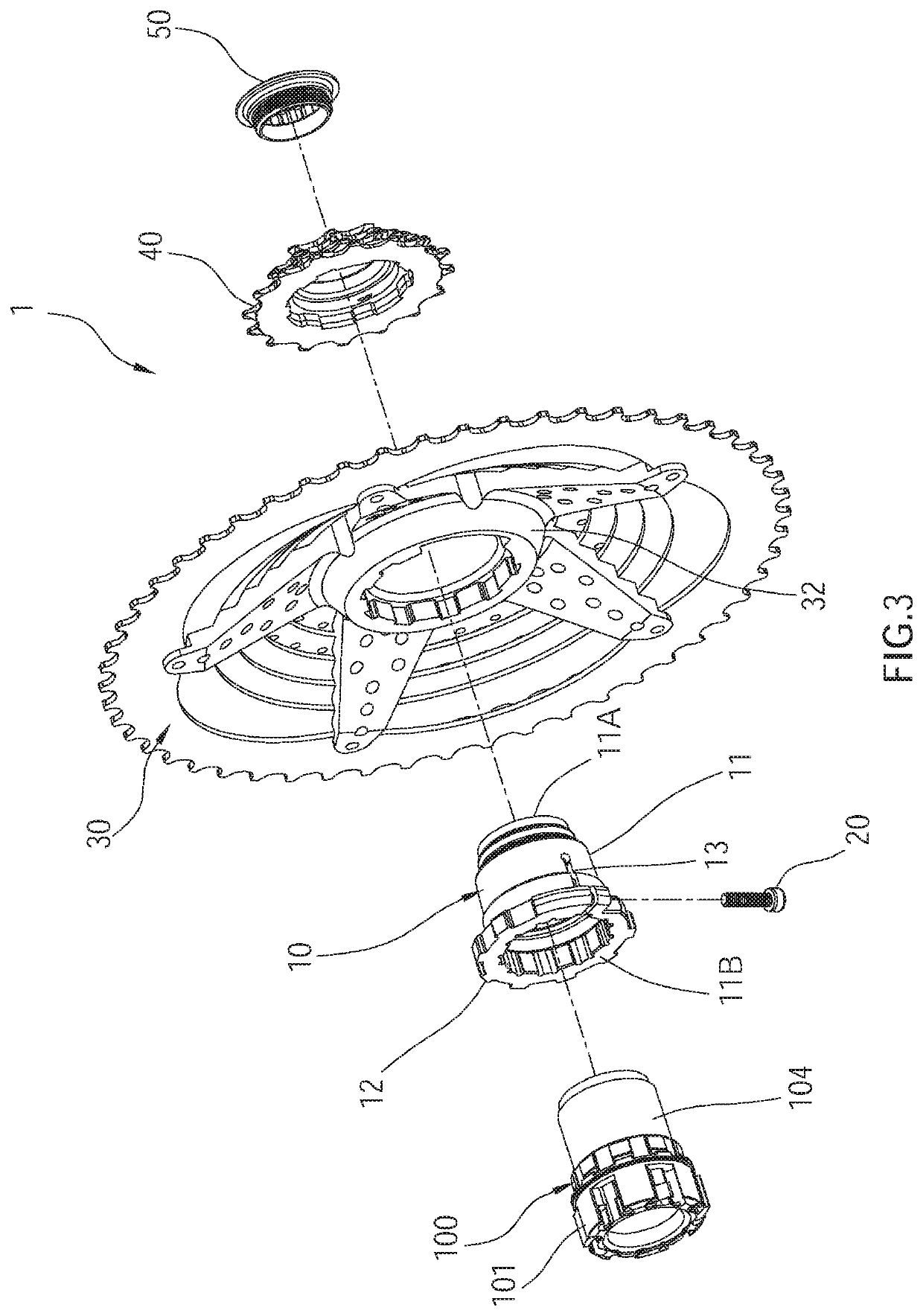
[0048]As shown in FIG. 1 to FIG. 3, a first embodiment of the present disclosure, a bicycle transmission device 1, is provided to be connected to a freehub body 100, wherein the freehub body 100 is used to be coaxially connected to a rear wheel of a bicycle (not shown). The junction of the freehub body 100 and the rear wheel has a joint part 101 which is used as a unidirectional ratchet to be connected to the rear wheel of a bicycle. Furthermore, when the freehub body 100 rotates in a driving direction, it can drive the rear wheel to rotate, while when the freehub body 100 rotates in a non-driving direction which is opposite to the driving direction, it will not drive the rear wheel to rotate; the structure is not described in detail herein because it is not the focus of the present disclosure. In the preferred embodiment of the present disclosure, as shown in FIG. 4, the freehub body 100 has a peripheral part 102 and a plurality of convex keys 103 arranged radially along the periph...


PUM


Abstract

A bicycle transmission device for connected to an freehub body on a rear wheel, which has convex keys arranged radially on the periphery, is provided, including a connecting member, a fastener, and a cogset assembly. The connecting member includes a cylindrical body portion, connection keys protruding from periphery of the body portion, a cut groove passing through the body portion, a first and second connecting seats located on two sides of the cut groove. The inner wall of the body portion has concave grooves corresponding to the convex keys. The fastener is connected to the connecting seats to exert a force making them close. The cogset assembly includes a cogset seat and sprockets. The cogset seat has a first socket hole fitting around the connecting member, and connection grooves corresponding and connected to the connection keys; the sprockets with different chain teeth are connected to the cogset seat.

Description

BACKGROUND OF THE INVENTION1. Technical Field[0001]The present disclosure relates generally to bicycles, and more particularly to a bicycle transmission device.2. Description of Related Art[0002]With the popularity of bicycles, bicycle transmission devices have become more diverse in structural design. In common bicycle transmission device as disclosed in the specification and FIG. 10 of U.S. Pat. No. 9,771,127, the connecting member installed on the rear wheel has external screw threads, while the adapter has internal screw threads corresponding to the external threads, so that the adapter can be screwed onto the connecting member; in addition, the sprocket is fixed on the outside of the adapter. Thus, when the chain drives the sprocket to turn, the turning force of the sprocket will be transmitted to the adapter, and then to the connecting member through the screw lock, which drive the rear wheel to rotate.[0003]However, said turning force is transmitted through the matching screw...

Claims


Application Information

Patent Timeline
Patent Type & Authority Applications(United States)
IPC IPC(8): B62M9/10F16D1/08
CPCB62M9/10F16D2001/103F16D1/0847F16D1/0864B60B27/023B60B27/04
Inventor TSAI, VINCE
Owner TIEN HSIN INDS
Learn More