Connector with cap

Active Publication Date: 2021-11-04
YAZAKI CORP
View PDF0 Cites 2 Cited by
  • Summary
  • Abstract
  • Description
  • Claims
  • Application Information

AI Technical Summary

Benefits of technology

[0013]The present disclosure has been made in view of the above circumstances, and an object of the present disclosure is to pr

Problems solved by technology

When the chamfered portion is provided at the opening end portion of the terminal accommodating portion 541 in a manner of avoiding the interference, a thickness of the opening

Method used


Image

  • Connector with cap
  • Connector with cap
  • Connector with cap

Examples


Example

[0031]Hereinafter, an example of an embodiment according to the present disclosure will be described with reference to the drawings.

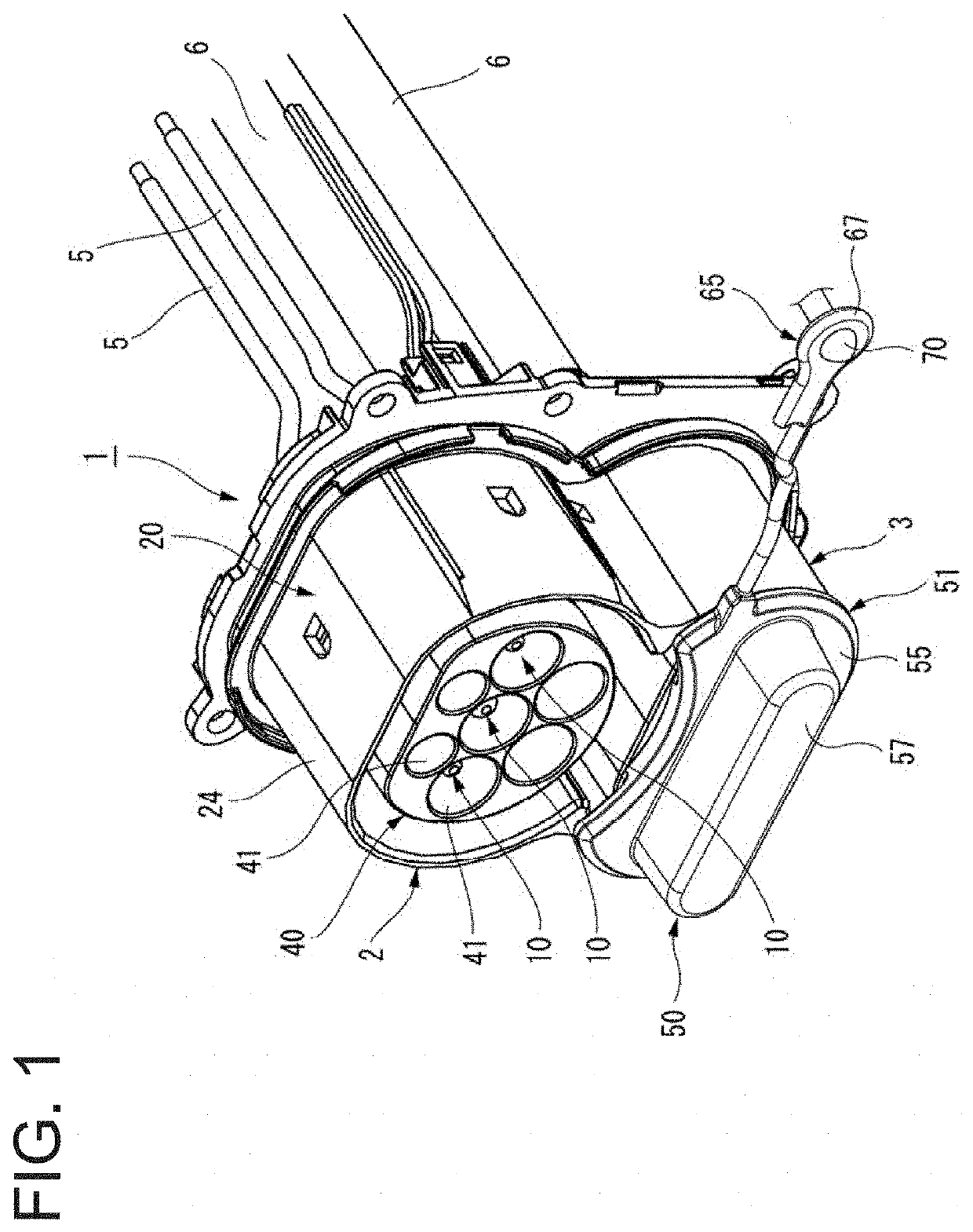
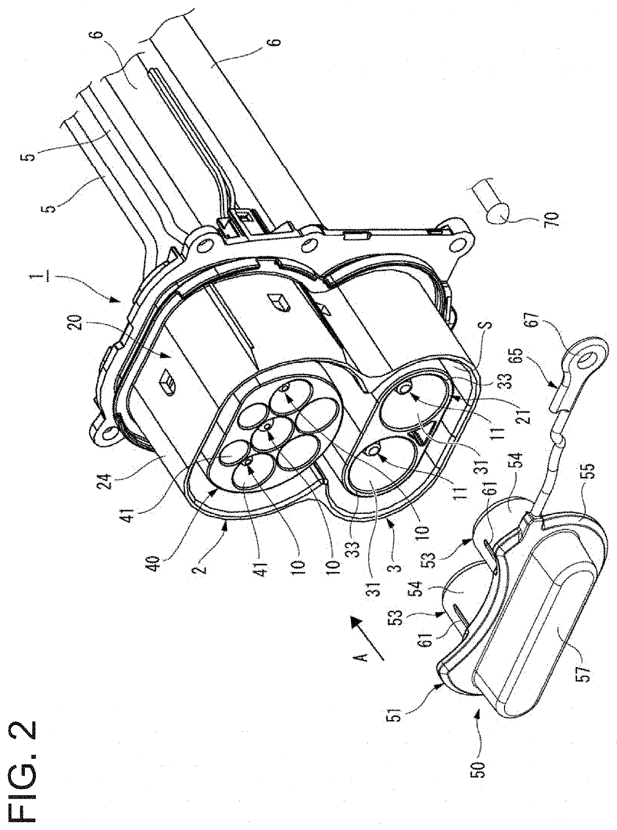
[0032]FIG. 1 is a perspective view showing a connector 1 with a cap (hereinafter, simply referred to as the connector (1)) according to an embodiment of the present disclosure. FIG. 2 is an exploded perspective view showing the connector 1 shown in FIG. 1.

[0033]The connector 1 according to the present embodiment is, for example, a connector mounted in a vehicle such as a hybrid vehicle or an electric vehicle and is a vehicle-side connector to be fitted to a charging connector (counterpart connector). The connector 1 according to the present embodiment includes a normal charging connector 2 for normal charging and a quick charging connector 3 to be fitted to a charging connector for supplying a direct current.

[0034]The quick charging connector 3 is detachably provided with a cap 50 that can cover a terminal accommodating portion 21 when quick charging is...


PUM


Abstract

A connector includes a connector housing and a cap. The connector housing has a terminal accommodating portion formed with a bottomed tubular cavity. The cap has a cap body configured to cover an opening portion of the cavity, a tubular portion vertically provided on a rear surface of the cap body and configured to be fitted into a tubular inner surface of the cavity in a fitting direction, a contact portion facing an opening edge portion of the cavity, provided on the cap body, and located outward than a root of the tubular portion in a radial direction of the cap body, and a recessed portion provided on the rear surface of the cap body between the root of the tubular portion and the contact portion.

Description

CROSS-REFERENCE TO RELATED APPLICATIONS[0001]This application is based on and claims priority under 35 USC 119 from Japanese Patent Application No. 2020-081343 filed on May 1, 2020, the contents of which are incorporated herein by reference.TECHNICAL FIELD[0002]The present disclosure relates to a connector with a cap.BACKGROUND ART[0003]In order to charge a battery of an electric vehicle or a plug-in hybrid vehicle, a vehicle-side connector to be fitted to a charging connector connected to an external power supply is provided at a vehicle side.[0004]This type of vehicle-side connector is provided with a cover member (cap) that covers an opening portion of a connector housing so that water or dust does not enter the connector when the connector is not in use (see JP-A-2017-204431 and the like).[0005]As shown in FIG. 7, such a connector 515 includes a connector housing 540 that accommodates a male terminal 520 and is provided with an opening portion 545 at a tip side of the male termi...

Claims


Application Information

Patent Timeline
IPC IPC(8): H01R13/506
CPCH01R13/506H01R2201/26H01R13/502H01R13/5213B60L53/16
Inventor KANAMORI, TAKANORITSUSHIMA, YOSHITAKA
Owner YAZAKI CORP
Why Eureka
Try Eureka